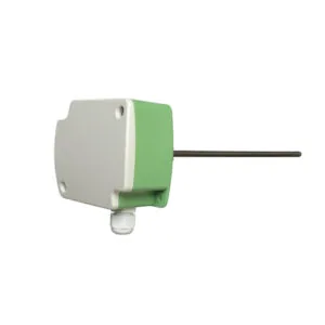
DSAE-2101 


| Model | DTHE-2001 |
|---|---|
| Sensor Type | Wall-mount temperature & humidity transmitter |
| Temp. Range | 0–50 °C (A) / -20–80 °C (B) |
| Temp. Accuracy | ±0.3 °C |
| Humidity Range | 0–100% RH |
| Humidity Accuracy | ±3% RH |
| Output Signal | 0–10 V (temp. & humidity) |
| Operating Temp. | -40–80 °C |
| Operating Humidity | 10–90% RH (non-condensing) |
| Supply Voltage | 15–35 VDC or 24 VAC ±20% |
| Working Current | 15 mA |
| Net Weight | 75 g |
| Housing Material | PC |
DTHE-2001 is a wall-mount temperature and humidity transmitter for indoor climate monitoring. It uses a Swiss SHT sensing element and a microcontroller to produce two independent 0–10 V outputs — one proportional to temperature, one to relative humidity — so a controller or building management system can read both variables from a single device on the wall.
The advantages of combining the two measurements in one housing are practical rather than technical. One cable run serves both channels, one mounting position serves both sensors, and the two readings are taken in the same air at the same moment, which matters for any control strategy that compares them — a room whose humidity climbs while the temperature falls is a different problem from one where both rise together. The housing is a compact PC enclosure intended for indoor wall mounting in the occupied zone.
The sensing element carries both measuring functions on a single die: a band-gap temperature sensor and a capacitive polymer humidity sensor, with the signal conditioning and calibration data held in the same package. That construction is why the two channels stay aligned with each other over time rather than drifting apart, which is the usual weakness of pairing two separate instruments in one enclosure.
Each channel drives its own output across its own range, so the temperature loop and the humidity loop are scaled independently. The published long-term stability figures — better than 0.04 °C per year for temperature and better than 0.5 % RH per year for humidity — describe how far the readings can be expected to drift from calibration as the sensor ages. They are the reason this class of transmitter is normally installed once and left alone, rather than being scheduled for annual recalibration; where a calibration is required by a validation protocol, the drift figures tell you what the interval can reasonably be. Response time is one second on both channels, with a resolution of 0.1 °C and 0.1 % RH.
Two temperature ranges cover the usual duties: 0–50 °C for comfort applications such as offices, hotels and residential interiors, and -20–80 °C for cold rooms, atria and other spaces that operate outside the comfort band. Custom ranges are available, which is worth knowing where a project’s control system expects a specific span; the sensor range selector helps match a range to the application before an enquiry is issued.
The humidity channel spans 0–100 % RH as standard, with an accuracy of ±3 % RH stated to include non-linearity, hysteresis and repeatability — the three error sources that a single accuracy figure otherwise hides. The supply is 15–35 VDC or 24 VAC, matching the common panel voltages, and the working current is low enough for a single supply to feed several transmitters on the same floor.
Typical installations are building automation and HVAC signal acquisition, greenhouses and plant propagation rooms, and pharmaceutical or chemical environments where indoor climate is recorded. In commercial buildings the pair of readings is used for comfort control, for monitoring a space where humidity is the limiting condition — museums, laboratories, print rooms, food preparation areas and data rooms — and for detecting the conditions that lead to condensation on cold surfaces.
In horticulture and process monitoring the humidity channel often carries more weight than the temperature channel, because evapotranspiration and drying rates follow the moisture content of the air rather than its temperature alone. That is a case where a combined transmitter is genuinely more useful than two separate instruments, since the two variables are read in the same air and can be used together in a single control calculation.
Decide first what the reading is for. If the answer is comfort control, the 0–50 °C range with ±0.3 °C accuracy is appropriate and the humidity channel is used for monitoring and condensation risk. If the space operates below zero or above comfort temperature, the wider range is required, and its stated accuracy should be checked across that wider span. If the answer is a validation protocol or a product-quality record, the humidity accuracy figure and the long-term stability become the deciding parameters, because both are quoted in a way that can be defended in an audit.
Second, confirm that the controller can accept two analogue channels at that point. A combined transmitter saves a mounting position and a cable run, but it still needs two inputs, and a project whose controller has one spare input should either take the channels separately or use a different arrangement. Third, decide the siting before anything is ordered — the most accurate transmitter in the catalogue cannot compensate for being mounted above a radiator, beside a door or in direct sun. Signal conventions are discussed in HVAC control signals: 0–10 V and 4–20 mA, the analog signal calculator converts a reading into the voltage each channel will present so that the controller scaling can be written down before commissioning, and the choice of sensing element itself is discussed in PT100 vs NTC vs digital output. The wider family is listed under the sensor range.
Mount the transmitter 1.2–1.5 m above the floor on an interior wall that is representative of the occupied zone. Keep it clear of direct sunlight, door draughts, supply diffusers, radiators and other local heat sources, and out of the dead air in a corner or behind furniture, because a wall sensor measures the air immediately around it and that air is the only thing it can report. Where the room has a strong stratification, a duct or averaging sensor elsewhere in the system may be the better measurement point.
The device is a multi-wire transmitter: supply, common, and one signal conductor for each channel. Use screened cable for the signal pairs where the route passes near variable-speed drives or mains, earth the screen at the panel end only, and terminate the two channels in separate controller inputs so that a fault on one loop is visible as a fault rather than as an unexpected reading on the other. Commission by comparing both channels against a reference instrument at a known condition, which also confirms the controller’s scaling for each range.
Because temperature and humidity are two independent measurements that are usually used for different purposes and often in different control loops. A single combined signal would have to compress both into one voltage, which is neither a standard convention nor readable by the analogue inputs that controllers and building management systems actually provide. Two outputs let each variable be scaled across its own full range and wired to its own input.
1.2–1.5 m above the floor on an interior wall that sees the occupied air, away from sunlight, door draughts, supply diffusers and heat sources such as lamps, televisions or radiators. Avoid corners, the space behind furniture and the wall directly beside a door, because those positions report air that has little to do with the space the occupants occupy.
The long-term stability figures — better than 0.04 °C per year and better than 0.5 % RH per year — indicate that drift is slow enough for the transmitter to be installed and left in service. Where a project requires documented calibration on a fixed interval, those figures justify a multi-year interval rather than an annual one; where no such requirement exists, the practical approach is to re-verify the reading when a control problem is suspected rather than on a calendar.
Use a wall transmitter when the variable of interest is the air in an occupied space — that is what the occupants experience. Use a duct transmitter such as the DSTE-1001 when the variable is the air being delivered by an air handling unit, or when the room stratifies so strongly or is so large that a single wall position cannot represent it. Both are legitimate; choosing the wrong one produces a control loop that works against the actual condition.
It provides the two inputs that a condensation calculation needs — air temperature and relative humidity — which together give the dew point. Comparing that dew point with the surface temperature of a cold pipe, a chilled beam or a window is how a control system decides to raise the supply temperature or reduce the humidity before condensation forms. The transmitter itself measures the air; the decision belongs to the controller.
DNARENS supplies the DTHE-2001 for catalogue orders and as part of instrument packages alongside the duct transmitters, controllers and terminal valves used on the same project. Labelling, custom temperature ranges, cable length and packaging can be adapted for OEM and project business, and transmitters can be supplied as a schedule matched to the point list on the drawing. Because the range and the number of signals are the two parameters that determine whether a transmitter fits a project, send the point list with the required ranges and channels and an accurate schedule can be prepared from it. More on our OEM/ODM work is in your reliable OEM/ODM partner for smart HVAC controls.
Tell us your required quantity and specifications — we reply within 24 hours.