A fan-coil unit thermostat is a small device with a large responsibility: it decides when the fan runs, when the valve opens, and how comfortable the room feels. Most service calls traced to a “faulty thermostat” turn out to be wiring or configuration issues that a careful commissioning routine would have caught.
This field guide covers the terminal layout and wiring practice, the system details you have to establish before the first wire is terminated, a step-by-step commissioning sequence, a commissioning record you can fill in on site, and the fastest checks for the faults installers meet most often. If the cable is not in the wall yet, start with our central AC thermostat installation and wiring guide instead — this article assumes the installation is done and the job now needs proving.
What You Need Before You Start
- The unit wiring diagram and the thermostat terminal legend — do not work from memory across models
- A multimeter capable of measuring AC/DC voltage and resistance, plus a calibrated reference thermometer
- Confirmed supply: 24 V AC from a transformer, or 85–250 V AC line voltage — verify before connecting anything
- Valve type on site: on/off (two-wire or three-wire), or modulating (0–10 V)
- Fan type: three-speed AC, or an EC motor driven by a 0–10 V speed signal
- The pipe configuration: two-pipe changeover, or four-pipe with separate heating and cooling coils
- The supervisor settings, where Modbus or BACnet is in use: address, baud rate and parity
Confirming these seven items before the first wire is terminated prevents most of the damage and rework that happens on site. Six of them can be read off the as-built drawings. The seventh — the pipe configuration actually installed — is worth a walk to the riser to check, because on retrofit work the drawings are frequently out of date.
Identify the System Before You Wire
The terminal count tells you very little on its own. Two thermostats with identical terminal blocks can need completely different configuration, and a mis-set parameter is the single most common reason a correctly wired unit behaves as though it is dead.
If the thermostat itself has not been chosen yet, our guide to temperature controller selection covers the criteria in detail. The rest of this article assumes the unit is already on the wall and the job now has to be proven.
| What to establish | Options you will meet | How it changes the wiring |
|---|---|---|
| Pipe configuration | Two-pipe (heating or cooling, selected by season) or four-pipe (both, on separate coils) | Four-pipe needs two valve outputs and a mode that lets heating and cooling be requested independently |
| Valve type | On/off two-wire, on/off three-wire, or modulating 0–10 V | Decides whether the thermostat switches a live output or sends an analogue signal with a common reference |
| Fan type | Three-speed AC motor with tapped windings, or an EC motor with a 0–10 V speed input | Three-speed uses three switched conductors; EC uses one signal pair and no speed switching at all |
| Supply | 24 V AC from a local transformer, or 85–250 V AC line voltage | Line-voltage units must not share a back box or a conduit with low-voltage signal wiring |
| Control signal | Standalone, Modbus RTU (RS-485), or BACnet MS/TP | Bus units need correct termination, consistent polarity and an address that matches the supervisor |
| Changeover source | A local pipe-mounted changeover sensor, or a central command from the BMS | Determines whether a two-pipe unit decides its own season or follows a plant-level signal |
Write the answers down before you start. The same table then becomes the front page of the commissioning record at the end of the job, and it is what the next engineer will read when the unit is reported faulty two years later.
Terminal Layout and Wiring
Terminal markings vary between manufacturers, but the functional groups are consistent. Our FCU thermostat range follows the same convention — supply and fan on one side, valve outputs and sensor inputs on the other — so that mains and signal conductors stay physically separated inside the enclosure.
Power and Fan Terminals
- L / N (or 24 V / COM) — supply. Respect the voltage rating on the thermostat nameplate; a 24 V unit wired to line voltage is destroyed on first energisation.
- Fan speeds — usually High / Medium / Low, switching the fan winding or a speed relay. On EC motors a single 0–10 V output drives speed instead, and the three speed terminals are left unused.
- Fan enable — on some models a separate dry contact starts the fan independently of the speed demand, which is how fan-cycled and fan-continuous logic is implemented.
- Valve outputs — one or two switched outputs for heating and cooling valves, or a 0–10 V modulating output.
Valve Outputs
- On/off valves (2-port) — switched live output to the actuator; the actuator return goes to neutral.
- On/off valves (3-port) — check whether the application needs diverting or mixing logic, and wire the actuator accordingly.
- Modulating valves — a 0–10 V signal plus a common reference. Keep signal cable away from mains wiring to avoid induced noise.
The actuator on the other end of the cable matters as much as the terminal you land it on. The four types below cover the great majority of fan coil installations:
| Actuator | Conductors to the valve | How the thermostat drives it | Typical commissioning note |
|---|---|---|---|
| On/off two-wire (2-port, spring return) | Switched live, neutral | Output energised to open, de-energised to close by spring | If it does not move, measure at the actuator terminals — not only at the thermostat |
| On/off three-wire (3-port) | Open, close, common | Two switched outputs; the thermostat must be set for diverting or mixing | Wrong port powered drives the valve the wrong way or stalls it against the seat |
| Modulating 0–10 V | Signal, reference, and often a separate 24 V supply | Analogue voltage proportional to demand | Partial stroke or hunting usually means a missing reference or signal noise |
| Thermal / thermal-electric | Switched live only | Slow, silent operation on a wax or bimetal element | A two to three minute delay after a demand change is normal, not a fault |
If the valve is on the chilled-water side, confirm the coil can actually deliver the duty before you spend the afternoon on the controls: our fan coil flow and ΔT calculator converts between coil load, water flow and supply-to-return difference, and a coil that never reaches its design ΔT will look exactly like a control fault from the room.
Sensor and Communication
- Built-in sensor — most room thermostats sense locally; keep the unit out of direct sun, away from supply air and away from internal heat sources.
- Remote sensor — connect to the dedicated input using the correct type (NTC 10 kΩ or PT1000 depending on model).
- Communication — where Modbus or BACnet is fitted, terminate the bus correctly, keep polarity consistent, and confirm the address and baud rate match the supervisor configuration.
| Sensor | Where it is used | What to verify on site |
|---|---|---|
| Built-in NTC | Room thermostat, local sensing | Free air circulation, 1.5 m above floor, clear of supply diffusers and direct sun |
| Remote NTC 10 kΩ | Return-air plenum, concealed or tamper-resistant mounting | The sensor curve matches the thermostat configuration — a mismatched curve reads plausibly but wrongly |
| PT1000 | Higher accuracy, plant-side monitoring | Correct type code, and two- or three-wire compensation exactly as specified |
| Changeover sensor (pipe clamp) | Two-pipe changeover control | Clamped to the pipe and insulated, on the pipe that actually carries the active season |
Wiring Practice Notes
- Use the conductor size stated in the project specification, and check that the terminal will accept it before the cable is pulled.
- Do not run signal and mains cable in the same conduit. Where a crossing is unavoidable, cross at right angles rather than running parallel.
- Use shielded twisted pair for 0–10 V and bus wiring, and earth the shield at one end only.
- Torque terminals to specification. A loose neutral is one of the classic intermittent faults, and it rarely shows up at the moment of testing.
- Add up actuator inrush before sharing a 24 V transformer. A transformer that is fully loaded on paper will sag in practice.
- Leave a service loop so the thermostat can be removed and re-fitted without re-terminating the conductors.
- Label both ends of every conductor before pulling, not afterwards.
Step-by-Step Commissioning
- De-energise and check continuity. With power off, verify there are no shorts between live, neutral and earth, and confirm the valve actuator coil resistance is within the datasheet range.
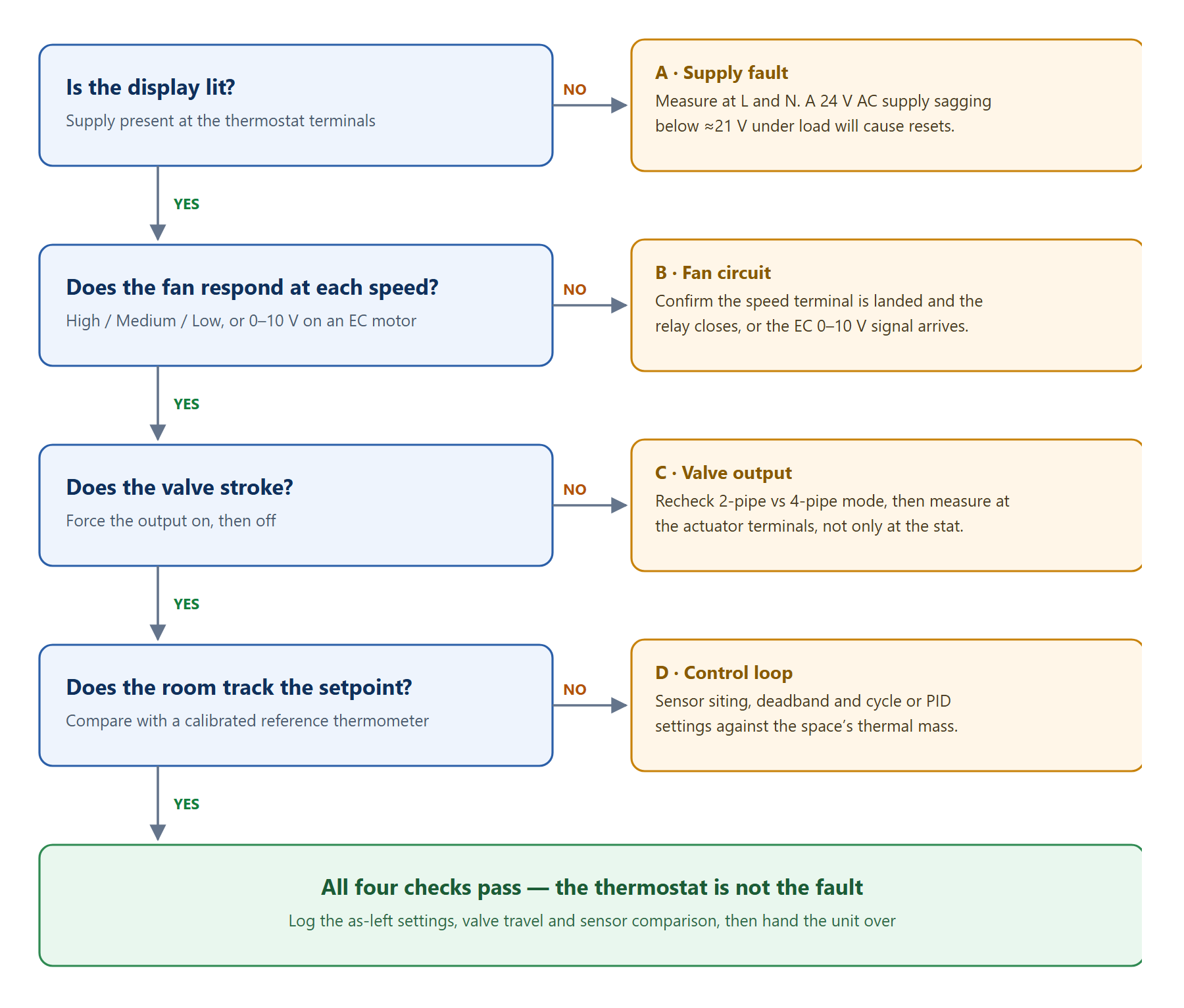
- Energise and verify supply. Measure the voltage at the thermostat supply terminals. A 24 V transformer sagging below about 21 V under load will cause resets and erratic behaviour.
- Set the configuration. Choose heating or cooling mode, two-pipe or four-pipe, fan behaviour (continuous or cycled with demand), and the temperature scale and setpoint limits.
- Test the fan. Step through High, Medium and Low and confirm the motor actually responds at each speed. On EC motors, verify the 0–10 V output reaches the expected voltage at each step.
- Exercise the valve. Force the output on and confirm the valve opens, then off and confirm it closes. On modulating valves, drive 0 %, 50 % and 100 % and check the travel matches.
- Verify sensing. Hold a calibrated reference thermometer beside the sensor and compare. A difference beyond about 1 °C calls for relocation or replacement.
- Run a demand cycle. Set the setpoint 3 °C above room temperature and confirm the system calls for heating, the valve opens and the fan behaves as configured. Repeat the test in cooling.
- Check the water side. With the valve fully open and the coil at design load, confirm the supply-to-return difference is close to the design value. A coil that is air-bound, fouled or undersized cannot be fixed at the thermostat.
- Record the results. Log the as-found and as-left settings, the sensor comparison and the valve travel. That record is what makes the next service call quick.
The Commissioning Record
Most callbacks are not new faults — they are old ones that nobody wrote down. A one-page record costs ten minutes on site and saves an hour on the next visit, and it is what separates a commissioning visit from a testing visit. The fields worth capturing on every unit:
| Item | Typical entry | Why it matters |
|---|---|---|
| Supply voltage at the thermostat | 23.8 V AC | A transformer at the edge of its rating drifts lower over time |
| Valve actuator resistance | 320 Ω | A coil outside the datasheet band predicts a failure you can still prevent |
| Fan speeds confirmed | Low / Med / High verified | Proves the tapped winding and the speed relay are both intact |
| Valve travel at 0 / 50 / 100 % | 0.0 / 4.9 / 9.8 V at the actuator | Catches a binding stroke before the occupant notices it |
| Sensor deviation vs reference | +0.4 °C | Anything beyond about 1 °C needs relocation, not recalibration |
| Mode and fan logic | Four-pipe, fan cycled with demand | These two settings are the ones most often left wrong |
| Bus address and baud rate | 12, 9600 8N1 | A mismatch surfaces weeks later as an offline device |
| Demand cycle, heat and cool | Both passed | The end-to-end proof that the job is finished |
On a multi-floor replacement programme the same fields are captured floor by floor, and the pattern of results tells you more than any single reading. For a worked example of that approach, see the Kuala Lumpur Tower communicating thermostat retrofit.
Common Faults and Fast Checks
Work through the four questions below in order. Each one narrows the fault to a subsystem, and very few genuine thermostat failures survive to the bottom of the sequence.
| Symptom | Most likely cause | First check |
|---|---|---|
| Display lit but no output | Mode set two-pipe when the system is four-pipe, or the setpoint is already satisfied | Configuration mode, then compare the displayed room temperature with a reference thermometer |
| Fan runs constantly | Fan configured for continuous rather than cycled operation | The fan logic setting first, then the deadband — it is the more common cause by a wide margin |
| Valve hums or buzzes | Supply or wiring problem at the actuator, or a stalled motor | Voltage at the actuator terminals, measured under load |
| Room overshoots the setpoint | Sensor poorly sited, or deadband and cycle time too tight for the thermal mass of the space | Sensor location relative to supply air and sunlight, then widen the deadband |
| Modulating valve hunts | Signal noise from a cable run alongside mains, or PID values unsuited to the valve size | Cable routing and shielding first; tuning second |
| Intermittent resets | Undersized transformer, loose neutral, or too many actuators on a shared transformer | Supply voltage while all actuators are energised — a static reading will look normal |
| Valve opens but the room stays warm (or cold) | Water side: air, fouling, a closed balancing valve, or a coil that is undersized for the load | ΔT across the coil at full flow — if it is far from design, the thermostat is not the problem |
| Comfort drifts after a season change | Two-pipe changeover not following the plant, or a changeover sensor reading the wrong pipe | Changeover source and sensor position on the pipe |
| Bus device shows offline | Address or baud rate mismatch, reversed polarity, or missing termination | Address and baud rate against the supervisor, then polarity along the segment |
Summary
A reliable fan-coil installation comes from doing the simple things in order: establish the system type before wiring, confirm supply and load before energising, keep signal cables separate from mains, configure the mode and fan logic deliberately, then exercise fan, valve, sensor and water side before handing over. Record what you found and what you left behind. Most callbacks trace back to a step that was skipped rather than a component that failed — and a thermostat that has passed all four questions in the sequence above is very rarely the faulty part.
If a unit genuinely has failed, the fan coil thermostat range lists the push-button AC818, the touch-button AC3385 and the other models we build for fan coil applications, and the installation and wiring guide covers the terminal-by-terminal detail for mechanical and LCD types. For help matching a replacement to an existing valve and fan arrangement, talk to our engineering team.
Frequently Asked Questions
Can one thermostat control both a heating and a cooling valve?
Yes, on a four-pipe system with two independent valve outputs. On a two-pipe system a changeover sensor or a central changeover signal decides the season, and the single output serves whichever mode is active.
Why does the fan keep running after the setpoint is reached?
Either the fan is configured for continuous operation, or the sensor reading sits outside the deadband. Check the fan configuration first — it is the more common cause.
How high should a room thermostat be mounted?
Around 1.5 m above the finished floor, in a location with free air circulation, away from direct sunlight, supply diffusers, exterior walls and internal heat sources such as appliances or equipment.
Do I need a separate sensor for a fan-coil thermostat?
Most room thermostats use a built-in sensor. Where the unit is mounted in a return-air plenum, or the thermostat sits in a poor location, a remote NTC or PT1000 probe gives a more representative reading.
What voltage should I measure at a 24 V AC thermostat?
With the transformer unloaded you will typically see 24 to 27 V AC. Measure again with every valve actuator on the same transformer energised: anything below about 21 V AC under load means the transformer is undersized, the wiring is too long or thin, or a neutral connection is loose. Erratic resets and displays that flicker are far more often a supply problem than a faulty unit.
Can I replace a thermostat without draining the fan coil circuit?
Yes, in most cases. The thermostat only switches the actuator; the water circuit stays closed unless the actuator is removed from the valve body. Isolate the electrical supply at the local isolator, verify it is dead, and keep the wiring connections intact so the replacement can be landed on the same terminals. Drain the circuit only if the valve body itself is being replaced.
Why does the valve stay open when the thermostat is switched off?
Check the actuator type first. A spring-return actuator should close when the output is de-energised, so if it stays open the output is still live, the actuator is mechanically jammed, or the valve is installed in reverse relative to flow direction. On three-port actuators, confirm the thermostat is configured for the correct diverting or mixing logic — the wrong setting can hold one port open permanently.
How do I tell whether the system is two-pipe or four-pipe?
Follow the pipework from the fan coil. Two pipes entering the coil means the same coil carries heating in winter and cooling in summer, and the system needs changeover logic. Four pipes means separate heating and cooling coils, and the thermostat needs two valve outputs and an independent mode. Do not rely on the drawing on a retrofit — check the coil connection at the unit.
Need Help Specifying or Sourcing?
Tell us your system type, required quantity and target market — our engineers reply within 24 hours with matched models and a quotation.
Back to Blog