QBO3A 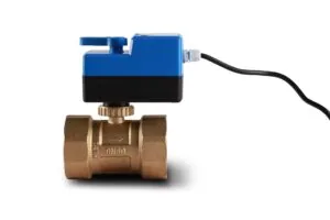


| Model | V2016 |
|---|---|
| Valve Type | 2-way normally closed / 3-way diverting motorized valve |
| Power Supply | AC 220 V ±10%, 50/60 Hz |
| Power Consumption | 6.5 W |
| Pressure Rating | 1.6 MPa |
| Opening Time | 8~12 s (attached) / 14~18 s (detached) |
| Closing Time | 3~5 s (attached) / 5~7 s (detached) |
| Ambient Temperature | 5~40 °C |
| Medium Temperature | 5~90 °C |
| Connection | BSP thread |
| Nominal Diameter | DN15~DN25 (G1/2″~G1″) |
| Kv Range | 2.0~6.8 |
| Differential Pressure | 0.15~0.2 MPa (model dependent) |
| Body Material | Forged brass |
| Actuator Cover | Stainless steel plate with aluminum cover |
| Return Mechanism | Stainless steel spring |
| Seal Material | Plastic EPT |
V2016 is a spring-return motorized valve for hot and chilled water circuits in heating, cooling and air-conditioning systems. It combines a forged brass valve body with an actuator that opens the valve electrically and closes it mechanically: a single-direction motor drives the valve open against a stainless-steel spring, and as soon as power is removed the spring returns the valve to its normally closed position. Both normally-closed two-way and diverting three-way versions are available, in DN15 to DN25.
The distinction between this valve and a power-open, power-close actuator is what happens when the electrical supply fails. On a conventional valve, a power failure leaves the valve wherever it happened to be, so a coil may continue to receive water with no control over it. On the V2016, the spring closes the valve, the coil stops receiving water, and the terminal simply stops conditioning — the failure mode is a loss of comfort rather than an uncontrolled load.
The actuator contains a motor that turns in one direction only. It drives the valve stem open and holds it there while the supply is present, compressing a stainless-steel spring as it goes. When the supply is interrupted — by the thermostat completing its cycle, by a controller failing, or by a power cut to the whole floor — the motor loses its magnetic field and the spring is free to drive the stem back to the seat. Closing therefore does not depend on the control system, on a signal, or on any stored energy in the building.
That property is what project engineers are buying when they specify a spring-return valve. In a four-pipe system it prevents a failed controller from leaving both coils open at once. In a chilled-water coil on an air handling unit it prevents condensate carry-over in the event of a fan or controller failure. In a heating circuit it prevents an unoccupied building from being held at temperature through a fault. The trade-off is the actuator cost and the fact that the spring must be recompressed on every opening stroke, which is why the opening time is longer than the closing time in the published figures.
Two-way normally closed is the standard terminal valve: it admits water to the coil when the thermostat calls and closes when the call ends or the power fails. Diverting three-way suits changeover and bypass circuits, where the flow has to be sent to one of two paths rather than simply stopped. The valve is also available with an optional microswitch that reports the valve’s position back to the controller, indicated by a suffix in the model number and useful where the control system needs confirmation that a coil is actually isolated rather than merely commanded to be.
The series is sized by connection and by Kv, and each combination has its own differential pressure capability, so the correct procedure is to establish the required Kv first and then confirm that the selected model can hold the branch closed against the pump. The following table lists the standard variants with their Kv and differential figures; the actuator and body are separable, so a valve can be replaced without a complete drain-down.
| Model | Connection | Configuration | Kv | Differential Pressure |
|---|---|---|---|---|
| V20162W1220 | G1/2 | Normally closed two-way | 2.0 | 0.2 MPa |
| V20162W1220A | G1/2 | Normally closed two-way | 2.0 | 0.2 MPa |
| V20163W1243 | G1/2 | Diverting three-way | 4.3 | 0.2 MPa |
| V20162W3432 | G3/4 | Normally closed two-way | 3.2 | 0.18 MPa |
| V20162W3432A | G3/4 | Normally closed two-way | 3.2 | 0.18 MPa |
| V20163W3446 | G3/4 | Diverting three-way | 4.6 | 0.18 MPa |
| V20162W1168 | G1 | Normally closed two-way | 6.8 | 0.15 MPa |
| V20163W1157 | G1 | Diverting three-way | 6.5 | 0.15 MPa |
Typical duties are fan coil unit water-side on/off control, air handling unit heating and cooling coils, underfloor heating manifolds, small commercial hydronic systems and zone control within a building automation scheme. The fail-safe behaviour is most valuable in the applications where an uncontrolled coil is genuinely a problem: cooling coils in humid climates, where an open chilled-water valve on a stopped fan produces condensate; heating coils in intermittently occupied buildings, where a stuck-open valve wastes energy all night; and two-pipe changeover installations, where a valve left in the wrong state can leave a room being cooled when it should be heated.
Because the body is forged brass with a stainless-steel spring and the actuator housing is a stainless plate under an aluminium cover, the valve also suits the ordinary working conditions of a ceiling void or a plant cupboard. The ambient temperature range that applies to the actuator is narrower than the medium temperature range that applies to the water, so the two should be checked separately when a valve is being installed close to a hot surface.
Start by asking what should happen when the power fails. If the answer is that the coil must stop receiving water, a spring-return normally closed valve is the correct specification, and the motor-open, spring-close arrangement is the only type that delivers it without depending on the control system. If the coil is a heating coil in a building that must not freeze, the same question usually leads to the opposite conclusion — and that is a system design decision to take deliberately rather than by default.
Then size the valve from the load. Calculate the required Kv from the coil’s design flow and available pressure drop using the control valve Cv / Kv calculator, select the nearest model from the table above, and check the differential pressure figure for that model against the pump head at the branch. Where a bypass or changeover circuit is involved, choose the three-way diverting version and confirm the piping arrangement matches. The general selection process, including the errors that only appear after handover, is set out in electric valve selection for HVAC: a practical guide, and the difference between this family and simpler switched valves is discussed in electric valve vs. solenoid valve. The alternatives sit under the electric valve range.
Install with the flow direction matching the arrow cast on the valve body, keep the ambient temperature within the range specified for the actuator, and allow enough clearance above the head for the actuator to be lifted off for service. Isolate the power before installation or maintenance, flush the piping system before commissioning, and avoid applying force to the actuator housing when tightening connections — the body takes the thread load. On a spring-return valve it is worth checking the closed position after wiring but before the system is filled, because the spring should return the stem with the supply removed and that is the one behaviour the whole specification depends on.
Where the actuator is fitted to an existing body, or the valve is being serviced in place, the actuator and body separate without tools, and the stroke times published for the attached and detached arrangements differ accordingly. Installation practice for terminal water valves is covered in motorized ball valve installation: 6 field precautions, and where a valve fails to respond, move or seal, the sequence of checks in electric ball valve troubleshooting applies to the actuator as well as to the body.
Because the failure mode is different. A power-open, power-close valve stays wherever it is when the supply fails, so the coil can be left open with no control over it. A spring-return valve closes under its own spring, so the coil stops receiving water even if the controller, the thermostat or the whole floor supply has failed. Where an uncontrolled coil is a real risk — condensate on a chilled coil, energy waste on a heating coil, or a changeover system in the wrong season — the spring-return version is the appropriate specification.
It indicates the optional microswitch feedback. The microswitch reports the valve’s actual position, so the control system can confirm that the coil is isolated rather than relying on the fact that it issued a close command. It is worth specifying on circuits where a false confirmation would be costly, such as a coil that has to be proven shut before another operation begins.
Yes. The actuator and valve body are separate assemblies that detach without tools, so a failed actuator can be exchanged with the pipework left in place. The stroke times differ between the attached and detached arrangements, which is why two sets of opening and closing times appear in the published data.
Choose two-way normally closed where the coil simply needs water or no water. Choose the diverting three-way version where the flow has to be sent down one of two paths: a two-pipe system changing over between chiller and boiler, or a bypass arrangement that has to keep water moving through the pump while a terminal is satisfied. The piping arrangement differs between the two, so the decision belongs with the system drawing rather than with the valve order.
From the flow and the differential, in that order. The required Kv follows from the coil’s design flow and the pressure drop the circuit can afford, which identifies the connection size; the differential pressure column then has to exceed the pump head at that branch with margin. If a model is adequate on Kv but its differential rating is close to the branch’s pump head, move up to the next model rather than accepting a valve that will fail to hold closed once the ball or plug has aged.
DNARENS supplies the V2016 series for catalogue orders and for project packages in which the terminal valves, thermostats and sensors are specified as one scope. Configuration, connection size, microswitch feedback, actuator labelling and packaging can all be adapted for OEM and project business, and valves can be delivered as a schedule matched to the coil duties on the drawing. For changeover and bypass circuits it is worth sending the piping schematic with the enquiry, because the three-way arrangement is the part most often specified incorrectly at tender stage. Send the coil loads, branch sizes, fail-safe requirement and available control voltage, and a valve schedule can be prepared against the project. More on our OEM/ODM work is in your reliable OEM/ODM partner for smart HVAC controls.
Tell us your required quantity and specifications — we reply within 24 hours.

