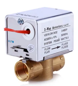
V6016 


| Model | QBO3A |
|---|---|
| Valve Type | Two-way motorized ball valve |
| Nominal Diameter | DN32-DN50 (other sizes available in series) |
| Power Supply | AC 24 V ±10% (AC 220 V optional), 50/60 Hz |
| Power Consumption | 2 VA (only during opening/closing) |
| Motor Type | Reversible synchronous motor |
| Running Time | 60 s / 100 s |
| Output Torque | 4 N·m (QB02A) / 8 N·m (QB03A) |
| Lead Wire Length | 700 mm (customizable) |
| Nominal Pressure | 1.6 MPa |
| Close-off Pressure | < 0.6 MPa |
| Connection | G-thread (BSPP) |
| Medium | Chilled water, hot water or 50% ethylene glycol solution |
| Medium Temperature | 2~70 °C / 2~90 °C |
| Protection Rating | IP54 |
QBO3A is a two-way motorized ball valve for the larger branches of a hydronic HVAC system. A reversible synchronous motor drives a brass ball through a quarter turn to open or close the flow path, and the actuator is sized for DN32 to DN50 connections — the range where a valve stops serving a single fan coil and starts serving a zone, a riser branch or a small chilled-water distribution loop.
The design choices suit that scale. The ball bore is straight through, so the open valve presents very little resistance to flow and debris passes rather than collecting on a seat; the motor is geared down to move the larger ball slowly and with more torque; and the closing action is deliberately unhurried, because a valve that slams shut on a DN50 line is a water hammer waiting to happen. Power is drawn only while the valve is actually travelling, so a zone that is open all season costs almost nothing to hold in position.
The actuator is a reversible synchronous type: one set of terminals drives the ball towards open, the other towards closed, and the motor stops at the end of travel. Because the valve only needs to be told which of two states to adopt, it is driven by a simple switched output from a thermostat, a zone controller or a building automation panel, which is what makes it straightforward to drop into an existing control scheme. As the valve is not a regulating device, the controlled variable in the loop remains the room or zone temperature rather than the water flow through the valve.
Two characteristics follow from the slow, geared drive. The first is water hammer: a ball valve that closes in a fraction of a second converts the momentum of the water column in a large pipe into a pressure spike, which is felt as a knock in the pipework and eventually damages joints and fittings. Closing over tens of seconds gives that momentum time to dissipate. The second is torque margin. A larger ball presents a larger contact area and a longer lever arm to the water pressure, so the actuator has to develop correspondingly more torque to turn it — which is why the published figure differs between the two actuator variants used across this size range.
Two build choices are made when the valve is ordered. The supply voltage is the first: AC 24 V is standard and AC 220 V is available as an option. Twenty-four volts is the usual choice in systems where the control panel already provides a 24 V supply, because it keeps switching inside the panel and avoids running mains to every valve position; the mains version suits retrofit work where 24 V is not available at the branch. Running time is the second: the actuator is available with different stroke times that correspond to the two torque variants in the range, and the slower, higher-torque version is the one for the largest bores and the highest differentials.
The connection is a G-thread (BSPP) fitting, and the medium may be chilled water, hot water or a 50 % ethylene-glycol solution, with the medium temperature range depending on the seat material specified. Actuator removal is tool-free at the coupling, so a failed actuator can be exchanged without draining the circuit — a detail that matters on a branch serving occupied space.
The natural duties are fan coil unit water-side control on branches feeding groups of units, air handling unit heating and cooling coils, small-zone chilled and hot water distribution, and commercial building HVAC retrofit projects where an existing manifold is being re-controlled by a new automation system. Because the valve accepts glycol mixtures, it is also usable on the frost-protected side of a system, which is common where a coil sits in an air stream that can drop below freezing.
Retrofit work is a significant part of the demand for this size: replacing a seized or leaking valve on a branch that is already piped requires a valve whose body length and thread match what is in the ceiling, and a G-thread BSPP connection is the standard the market expects. 24 V operation is often preferred for such work because the new control panel typically supplies 24 V even where the old valves were mains-operated.
Size the valve from the flow, not from the pipe. The pipe diameter tells you what will physically fit; the required Kv tells you what will actually control the load, and it follows from the design flow and the pressure drop the circuit can afford — the control valve Cv / Kv calculator performs that conversion. Then compare the branch’s differential pressure with the valve’s close-off rating: a pump with head left over at the branch will push water through a closed ball valve, and the resulting short-circuit defeats the whole point of the zone control.
After sizing, decide the control voltage and how the valve will be commanded. This model takes a switched open/close signal, which suits thermostat or zone-controller outputs; a project that requires proportional positioning needs a modulating valve instead, and the differences between the analogue signals are set out in HVAC control signals: 0–10 V and 4–20 mA. For terminal-sized branches below DN32, the DF220 covers DN20 and the V6016 and V2016 series cover DN15–DN25; the whole group is listed under the electric valve range. General selection practice is discussed in electric valve selection for HVAC.
Keep the actuator above the horizontal centreline of the pipe so that dust, condensate and any future weep at a joint do not collect in it, and avoid applying force to the actuator housing when tightening the union — the body takes the torque, not the head. Use G-thread fittings with a suitable sealant for parallel threads, and flush the branch before commissioning, because debris left from installation is the most common reason a ball valve fails to shut off cleanly later on. Wire according to the terminal legend and confirm the polarity of the open and close commands against the panel before the valve is stroked for the first time.
The field precautions that prevent most commissioning failures on ball valves — orientation, thread form, flushing and insulation clearance — are described in motorized ball valve installation: 6 field precautions, and the diagnostic order to work through when a valve stops responding is in electric ball valve troubleshooting.
Because the valve is much larger. A DN32–DN50 ball presents more area and a longer lever to the water pressure, so the drive is geared down to develop the torque needed, and the stroke time lengthens as a consequence. The slower closing is an advantage rather than a defect on a large branch: it lets the momentum of the water column dissipate instead of converting into a pressure spike that hammers the pipework.
AC 24 V is the standard build and is usually the better choice where the control panel already supplies 24 V, because switching stays inside the panel and no mains conductor has to be run to the valve position. The AC 220 V option suits installations where only mains is available at the branch, or where an existing mains-operated valve is being replaced without changing the wiring.
It lets the valve be positioned by hand when the actuator is not powered — during commissioning, when a branch has to be opened before the control panel is live, or in an emergency when a controller has failed and the zone must be isolated or restored quickly. Once the actuator is powered again it resumes normal operation.
The two actuator variants in this size range develop different output torques, and the higher figure is intended for the largest bores and the highest differential pressures. The reliable way to choose is to compare the torque (or the published close-off pressure) against the differential the pump will actually present at the branch, with margin for a dirty or aged ball. A valve that is marginal at commissioning will fail to seal within a season.
Yes. This model is rated for a 50 % ethylene-glycol solution as well as chilled and hot water, which is the usual frost-protection fill for coils exposed to air that can drop below freezing. The seat material determines the upper end of the medium temperature range, so the operating temperature of the loop should be checked against the variant being ordered.
DNARENS supplies the QBO3A for catalogue orders and as part of project packages that include the zone controllers and sensors working with it. For OEM and project business, actuator labelling, packaging and the supply voltage can be aligned with the customer’s control panel standard, and valves can be supplied as a schedule matched to the branch sizes on the drawing. Send the branch duties, connection sizes, available control voltage and any frost-protection requirement, and a valve list can be prepared against the project. Further detail on our OEM/ODM work is in your reliable OEM/ODM partner for smart HVAC controls.
Tell us your required quantity and specifications — we reply within 24 hours.