Overview
An HVAC control system is the layer of sensors, controllers and actuators that turns a mechanical plant into a system that holds conditions where people actually need them. The chiller, the boiler and the fan coil only decide how much heating or cooling is available. The control system decides how much is delivered, minute by minute, to each space.
Take that layer away and a building still runs — it simply runs flat out, all the time, with rooms that overshoot in spring and never quite catch up in August. Everything a controls engineer does sits in the gap between those two states.
This guide covers what the system is, what each part is for, the four blocks that every control loop reduces to, the signals that connect them, and how to diagnose the failures behind most valve automation call-outs.
Key points
- An HVAC control system has four parts: sensors that measure, a controller that compares and decides, actuators that move something physical, and the terminal device — a valve, damper or fan — that changes the output.
- Its purpose is to close the gap between setpoint and reality without wasting energy or wearing the mechanical plant out. Comfort, energy and equipment life are three outputs of the same loop.
- Every loop is the same four blocks. A fan coil, a VAV box and a chilled-water plant differ in scale and in the signal they use, not in structure.
- The signal is the specification. On/off, floating and 0–10 V actuators are not interchangeable — the controller’s output type decides which one you can use.
- Most “valve faults” are not valve faults. A valve that never reaches its commanded position makes the controller keep correcting, and the symptom appears as room-temperature swing.
What is an HVAC control system?
It is the instrumentation and logic that regulates heating, ventilation and air conditioning equipment so that temperature, humidity, pressure and air quality stay inside their design bands. In practical terms it answers one question continuously, for every zone in the building: given what the space is doing now, how much heating or cooling should this terminal deliver in the next few minutes?
The system is usually described in three layers, and it helps to keep them separate when something goes wrong:
- The field layer — sensors, thermostats, actuators and valves. Everything that touches air, water or a person. Roughly 80 % of the failures you will ever chase live here, and most of them are mechanical or wiring faults rather than logic.
- The control layer — the controllers and the control loops. Room thermostats, fan-coil controllers, VAV controllers, and the PI loops inside them. This is where setpoints, deadbands and output types are defined.
- The management layer — the BMS or building automation system. Schedules, alarms, trending, and the supervisory setpoints that the control layer obeys.
The distinction matters commercially as much as technically. The management layer is where a building owner spends the most money and sees the least direct effect on comfort; the field layer is where a specification error becomes a permanent complaint. A thermostat with an on/off output wired to a modulating valve, for example, is not a marginal design choice — it is a system that can never hold a setpoint.
What is the purpose of controls in an HVAC system?
The purpose is not simply “to keep the room comfortable”. Comfort is the visible outcome; there are three others that matter just as much over a building’s life, and a control system is judged on all four at once.
- Match output to load, continuously. A cooling coil’s duty changes through the day — morning pull-down, occupancy swings, changing outdoor conditions. The control loop varies flow or air volume to follow that load instead of running the plant at a fixed output.
- Hold conditions inside a band, not at a point. Real control has a deadband and a proportional band. Understanding that is what stops people chasing a 0.2 °C offset that no occupant can feel.
- Cut energy at part load. A modulating valve that trims flow lets pumps and chillers unload. An on/off valve delivers full flow or none, which is why a two-position valve on a cooling coil raises both energy use and temperature swing.
- Protect the plant. Anti-cycling timers, minimum run times, freeze protection, and return springs that fail a valve closed on a heating coil. These functions never show up in a comfort complaint, but they are the reason equipment lasts.
If you are evaluating a control scheme and cannot say which of these four a given device serves, the device is probably being specified for the wrong reason.
The control loop, step by step
Every terminal control problem, in a fan coil or in a chilled-water plant, reduces to the same four blocks and the signals between them. Walking the path in order is also the fastest way to diagnose a fault: find the last block whose behaviour is still correct and the problem is in the one after it.
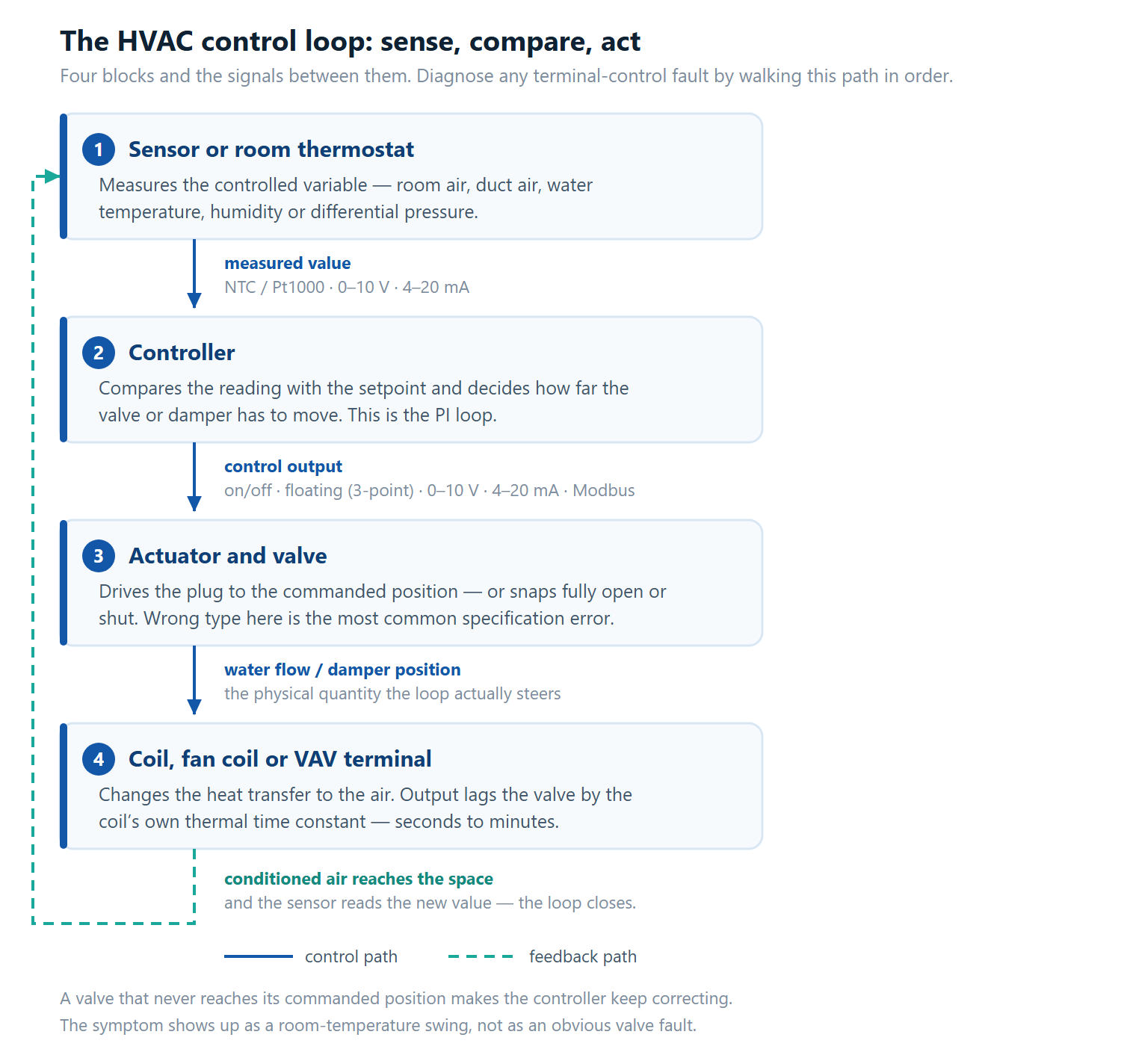
Three details of that loop explain most field behaviour:
- The loop only acts on what the sensor reports. A thermostat mounted in the return-air path or in direct sunlight measures its own environment, not the occupied space. Sensor placement is a control decision, not an installation detail.
- There is a delay at every hop. Valve stroke takes seconds to minutes; the coil responds over its own thermal time constant; the room responds over tens of minutes. The controller has to be tuned to the slowest element in the chain, which is why a fast-tuned loop with a slow actuator hunts.
- Feedback is what makes it a loop. Without the return path you have a sequence of commands, not control — and no way to notice that the valve stopped halfway.
On the water side, the sizing of that third block is what decides whether the loop can settle at all. Our control valve sizing calculator returns the Cv or Kv a valve needs from flow and pressure drop, and the nearest standard body — the number to specify from, rather than the pipe diameter.
Control signals you will actually see
The output type of the controller and the input type of the actuator have to match. This is the single most common interface error on site, and it is decided long before anyone arrives with a multi-meter — at specification stage.
| Signal | Wires | What it can do | Typical use |
|---|---|---|---|
| On/off (24 V) | 2 | Full open or full shut only | Safety isolation, small zone valves, humidifier control |
| Floating (3-point) | 3 | Any position, but no position feedback | Retrofit onto controllers with no analog output |
| 0–10 V | 2 + common | Any position, proportional | Fan coil and VAV terminals — the default in most new work |
| 4–20 mA | 2 | Any position, proportional, with live-zero fault detection | Plant-room loops and long cable runs where volt drop matters |
| Modbus / BACnet | 2 (bus) | Any position plus position readback and diagnostics | BMS-integrated installations where the valve reports for itself |
Two practical consequences are worth carrying into a specification:
- The signal tells you whether you can modulate at all. An on/off valve cannot be made to hold a partial position by any controller, and a floating actuator cannot report where it is. If the loop needs to hold a value, the signal has to be proportional or the actuator has to be intelligent.
- Scaling errors look like control faults. A 0–10 V actuator fed a 2–10 V signal will move, but across the wrong range — it will never fully close or fully open, and the room will drift. Check the signal range at the actuator terminals before you replace anything. Our analog signal calculator converts between 4–20 mA, 0–10 V, 2–10 V and 0–5 V and works out the value a signal represents.
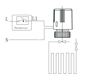
The actuator side of a fan coil is usually supplied as one assembly — body, motor and linkage — so the signal is fixed by the part number. That is why motorised valves and actuators are specified together, and why a thermostat with the wrong output type cannot be rescued later without changing hardware.
Valve automation troubleshooting: the failures behind most call-outs
Valve automation faults follow a short list of patterns. In almost every case the fault presents as something else — a room that will not settle, a coil that heats when it should cool — because the occupant notices the outcome, not the component.
| Symptom | What it usually means | Check first |
|---|---|---|
| Room temperature swings around setpoint | The valve never reaches its commanded position, so the controller keeps correcting for a move that did not happen | Command a full stroke and time it against the actuator’s rated travel time; compare against the loop’s tuning |
| Valve hums but does not move | Actuator torque is below the close-off requirement, or the stem has seized | Operate the manual override handwheel; measure the differential pressure the valve is closing against |
| Coil heats when it should cool | Actuator direction is reversed, or the controller output is inverted for the valve type | Watch the direction of travel on an open command; measure the signal at the actuator terminals, not at the controller |
| Zone never satisfies at full load | The valve is oversized relative to the coil, so most of its useful travel is compressed into a small band and control becomes almost on/off | Required Cv against rated Cv, and valve authority — below roughly 0.3 control turns erratic |
| Actuator completely dead | No output from the controller, an open circuit on a 4–20 mA loop, or a failed power supply | Measure at the actuator terminals; a 4–20 mA loop reading 0 mA is a broken wire, not a zero demand |
Three rules cut the diagnosis time sharply:
- Measure at the actuator, not at the controller. A correct output at the controller and nothing at the actuator means the problem is in the wiring — one of the few fault classes a BMS trend will never show you.
- Distinguish “not moving” from “not moving far enough”. A valve that travels 90 % of its stroke looks healthy on a trend and still prevents the loop from settling.
- Size on Cv, not on pipe diameter. Two DN25 valves with different trim can differ several times over in flow coefficient, and an oversized valve is a control problem that looks like a tuning problem.
Where the duty is genuinely binary — a safety cut, a fill line, a small on/off zone — a solenoid may be the better fit than a motorised valve, and the reverse is true wherever the loop has to hold a value. The comparison is set out in electric valve vs solenoid valve.
What to specify together
Terminal control works when the four blocks are chosen as one assembly rather than four separate line items. Use the duty first, then read across.
| Application | Valve / device | Actuator signal | Controller |
|---|---|---|---|
| 4-pipe fan coil, modulating | 2-way ball valve, DN15–DN25 | 0–10 V, or floating on older controllers | FCU thermostat with an analog output |
| 2-pipe fan coil, on/off | 2-way ball valve, DN15–DN25 | On/off 24 V | FCU thermostat, on/off output |
| Zone reheat coil | 2-way valve, DN15–DN20 | Floating or 0–10 V | Room thermostat with a reheat output and a return spring on the valve |
| VAV terminal | Damper actuator | 0–10 V | VAV controller, or the BMS where it owns the zone |
| AHU coil, larger bore | 2-way or 3-way valve, DN32–DN50 | 0–10 V or 4–20 mA | BMS analog output from the plant controller |
Three specification habits prevent most of what is described above:
- Match the valve to the coil, not to the pipe. Size on the required Cv and check the resulting valve authority. A valve that drops a large share of the circuit’s total pressure drop will control; one that drops very little will behave like an on/off device whatever signal you feed it.
- State the signal on both ends. Write the controller output type and the actuator input type into the schedule. “Modulating” is not a signal, and it is the word that hides the mismatch until commissioning.
- Decide the failure direction. A heating or reheat coil should fail closed; a cooling coil may safely stay in position. A return spring is a specification line item, and it is the one nobody notices until a freeze event.
A lot of this becomes concrete at project scale. The selection of air-conditioning systems for large complex projects walks through a mixed office-and-residential scheme where the water side, the terminal units and the control layer were specified together, including where separate water-loop heat pumps were preferred over a central four-pipe system.
Summary
An HVAC control system is the sense–compare–act layer that stands between a plant’s capacity and a room’s actual conditions. Four blocks, connected by signals whose type decides what the loop can physically do: measure the variable, compare it with the setpoint, drive a valve or damper, change the heat transfer to the air, and let the result come back as feedback.
For a terminal unit, that reduces to three questions you can answer at specification stage — does the loop need to hold a value, what signal does the controller provide, and is the valve sized on Cv with enough authority to control. Answer those and the commissioning visit is a verification; skip them and it becomes a redesign.
Work with DNARENS
DNARENS manufactures the terminal control layer these systems depend on:
fan coil thermostats, motorised valves and actuators, damper actuators, and temperature,
humidity and CO2 transmitters — from our own facility in Quanzhou, China, with
OEM and ODM support and 100% function testing before shipment.
If you are coordinating the water side of a project like this, these are the pieces that
sit between the plant room and the occupied space:
- FCU thermostats — line-voltage and
24 V room controllers for fan coil and four-pipe systems. - Motorised valves and actuators and
modulating damper actuators for zone control and
variable air volume terminals. - 0–10 V temperature, humidity and CO2
transmitters for fresh-air and IAQ strategies.
Send us the system type, quantity and target market and our engineers will reply within
24 hours with matched models and a quotation: contact the DNARENS
engineering team.
Free engineering tools, no sign-up: control valve sizing
calculator, FCU flow calculator,
damper actuator torque calculator,
analog signal calculator and
sensor range selector — all at
danrens.com/tools.
Need Help Specifying or Sourcing?
Tell us your system type, required quantity and target market — our engineers reply within 24 hours with matched models and a quotation.
Back to Blog