
Overview
An electric thermal actuator looks like a fitting you simply screw onto a manifold — and most of the time that is exactly what it is. The failures reported on site, though, are rarely electrical: an actuator seated on the wrong valve interface, forced on against its thread, or wired to a thermostat that never actually calls. This guide covers the installation procedure for a normally closed (NC) electric thermal actuator, the wiring that drives it, and the three clearance and dimension checks that decide whether it will still be working in three years.
The procedure below follows the E30 series normally closed thermal actuator — a wax-thermal advancer driven by PTC heating, rated AC 220 V / 230 V, 110 V or 24 V, 3.5 W, 110 N thrust, >3.0 mm stroke and a 6 min full travel time. The same sequence applies to any NC thermal actuator on a radiator, manifold or small valve, whatever the brand.
Key Points
- A thermal actuator is not a motor. A PTC-heated wax element expands and pushes a piston; a spring returns it when power is removed. There is no gearing to stall and no end switch to set.
- Stroke must be >3.0 mm to fully open or close the valve — a stem that only travels 2 mm will throttle the coil even when the actuator is at full travel.
- Mounting is vertical, onto the manifold port, then hand-tightened only. A tool on the union ring is the single most common cause of a split body.
- The interface is a 34.8 mm union nut on a M30 × 1.5 valve connection. Confirm both before ordering.
- Ambient rating is −5 °C to 60 °C, enclosure IP40. Above 60 °C — or on a hot-water riser with no air movement — the wax element drifts.
- NC means valve open when de-energised. Verify it against the coil you are controlling, not against the name of the actuator.
What an Electric Thermal Actuator Does
An electric thermal actuator is the drive element that opens and closes a small valve from a room thermostat signal. Inside the housing a wax-filled element sits against a PTC heater. Apply power and the element expands, pushing a piston down onto the valve stem; remove power and a return spring pushes the piston back. Because the motion is slow and the force is high but limited, the actuator is well suited to small valves — manifold branch valves, small two-port valves, dynamic balancing valves — and poorly suited to anything that needs fast or forceful movement.
The characteristics that follow from that design are worth understanding before you install one:
| Property | Value (E30 normally closed) | What it means on site |
|---|---|---|
| Drive principle | Wax thermal advancer (French-made element), PTC heating | Silent, no gearing. Nothing to lubricate and no stall torque to set. |
| Power supply | AC 220 V / 230 V ±10%, AC 110 V ±10%, AC 24 V ±10% | Three separate voltage versions — the model code decides which. Feeding a 24 V unit at 230 V destroys the element. |
| Power consumption | 3.5 W | Low enough that a wiring run does not need upsizing, but it is a continuous load whenever the valve is held open or closed. |
| Thrust | ~110 N | Adequate for small valves. If the valve needs more, the actuator is the wrong choice — not the wrong setting. |
| Stroke | >3.0 mm | Must exceed the valve stem travel with margin, or the valve never reaches its seat. |
| Full travel time | 6 min | Slow by design. Do not expect this actuator to respond to rapid load swings. |
| Ambient temperature | −5 °C to 60 °C | Sets the maximum temperature of the space the actuator body sits in — not of the water. |
| Enclosure | IP40 | Dust-protected, not water-protected. Keep it out of drip zones and washdown areas. |
| Return action | Spring return | The valve fails to its spring position on power loss — which is why the NC/NO designation matters. |
Two terms cause more confusion than any others. Normally closed (NC) describes the valve position with the actuator de-energised: the spring holds the valve shut, and power drives it open. Normally open (NO) is the opposite — the spring holds the valve open, and power closes it. The actuator you are installing is mechanically identical in both cases; what changes is the valve and the spring arrangement. Always confirm which one the coil needs before you mount anything.
Model and Control Wiring at a Glance
The illustration below is taken from the manufacturer installation sheet. It shows the three voltage variants and their ratings side by side, together with how a room thermostat (or an automatic temperature control device with an automatic start-stop function) connects through to the actuator.

Note the three specification blocks in the sheet are alternatives, not a menu. A single actuator is built for one supply voltage, and the model code carries that information. Read the code before you connect anything.
What You Need Before You Start
- Confirm the actuator is the voltage you think it is. 220/230 V, 110 V and 24 V bodies look identical. Applying the wrong supply is not a field-fixable fault.
- Confirm the valve interface. The E30 uses an M30 × 1.5 screw connection with a 34.8 mm union nut. Adapters exist, but a mismatched thread is the second most common installation failure.
- Check the stem stroke. The valve stem must travel >3.0 mm. Measure it on the bare valve before the actuator goes on — afterwards is too late.
- Check the ambient temperature. The actuator body must sit in a space between −5 °C and 60 °C. On an uninsulated hot-water manifold in a plant room, that upper limit is closer than it looks.
- Isolate the circuit and prove dead at the thermostat and at the actuator, then release any residual pressure on the manifold before you unscrew a union.
- Have the manifold port accessible from the front. The actuator is installed vertically onto the port, and you need hand room around a 34.8 mm nut. See the dimensions section below before you commit to a location.
Step 1 — Wire the Actuator to Its Thermostat
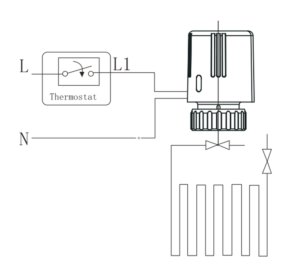
The actuator does not decide anything: it opens when the thermostat gives it power and closes when the power is removed. The wiring therefore reduces to a switched live through the thermostat contacts.
Working through the diagram:
- L (live in) lands on the thermostat’s supply terminal. This is the permanent live that feeds the switching contact.
- L1 (switched live out) runs from the thermostat contact to the actuator. When the thermostat calls, L1 becomes live and the wax element starts to heat.
- N (neutral) is common to the thermostat supply and the actuator. Both the actuator and the thermostat return through it.
| Check | Why it matters |
|---|---|
| Neutral goes to the actuator, not to the thermostat housing only | An actuator with a switched live but no neutral simply sits there. The circuit needs both conductors to return. |
| L and L1 are not swapped | The thermostat still switches, but it switches the wrong side of the load. It will appear to work and then fail during commissioning. |
| Earth continuity maintained to the valve body | Metal-bodied valves on a water system need the protective conductor intact. |
| Supply voltage matches the actuator model code | The single fault that cannot be corrected by rewiring. |
Because the element is PTC-heated, the actuator draws its rated 3.5 W continuously whenever the thermostat is calling — the wax element has to be held hot to stay expanded. This is normal, and the housing is designed to run warm. Do not add a timer or a pulsed supply to “save power”: the valve will simply never reach full stroke.
Step 2 — Mount the Actuator on the Manifold Port
This is the step where actuators get broken. The instruction is short, and every word of it matters: place the actuator vertically onto the manifold port, rotate clockwise, then tighten by hand.
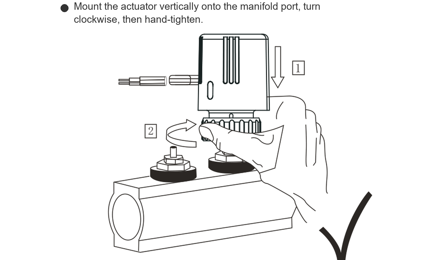
- Lower it vertically. Bring the actuator straight down onto the manifold port so the union nut engages the thread square. Angling it on risks cross-threading the M30 × 1.5 connection, which is fine-pitch and unforgiving.
- Rotate clockwise. Turn the body clockwise to start the thread by hand. If it binds within the first turn, stop and re-seat it — do not force it. The piston also needs to land centrally on the valve stem, and forcing a canted body will bend it.
- Tighten by hand only. Once the union nut is seated, tighten it firmly by hand. That is the whole torque specification. The seal is made by the union face, not by how hard the nut is pulled down.
- Check the piston seats on the stem. With the actuator fitted, the piston must sit on the centre of the valve stem, not on the edge of it.
- Do not use a wrench, a strap or a pipe on the union ring. The body is flame-retardant ABS with a PC cover over a reinforced PA66 internal assembly. It is strong in service and weak in torsion.
A related point that is easy to get wrong: mount the actuator with its axis vertical as shown, and leave enough clearance above it. The rear of the body has a small travel indicator window; if the actuator is jammed against pipework or a wall, you cannot see the position it is reporting, and you lose the one diagnostic the device gives you.
Step 3 — Check the Ambient Envelope and the Physical Dimensions
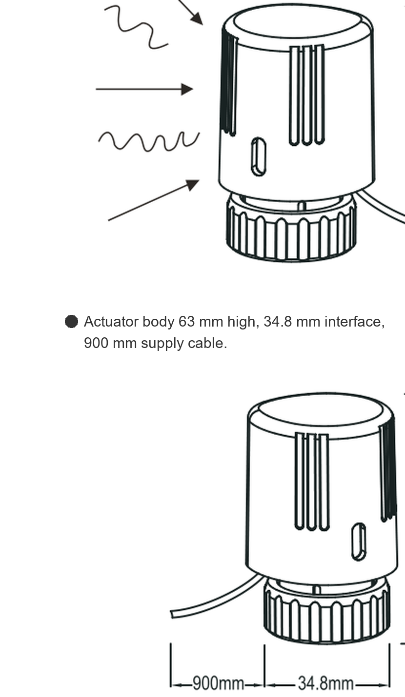
Two numbers decide whether the installation survives its first summer: the ambient temperature rating and the space the body actually needs.
| Dimension | Value | Planning consequence |
|---|---|---|
| Ambient temperature | −5 °C to 60 °C | This is the temperature of the air around the actuator body, not the water temperature. On a hot manifold in a poorly ventilated plant room, ambient can exceed water temperature during a shutdown. |
| Body height | 63 mm | Plus the union nut, this is what you need above the manifold port. Manifolds installed tight under a ceiling or inside a shallow cabinet often cannot take it. |
| Interface width | 34.8 mm | The hand-room envelope. You need fingers around this nut — the installation instruction assumes hand tightening, so the space has to allow it. |
| Cable length | 900 mm | Roughly 900 mm of flying lead from the body. If the nearest junction box is further away, plan a terminal box — do not extend the lead with a splice inside the actuator. |
| Enclosure rating | IP40 | Dust-protected only. A drip tray above the manifold, or a plant room that gets hosed down, will find this out. |
If the ambient temperature at the actuator is going to exceed 60 °C, insulation of the manifold is the correct fix — not a different actuator. Above that limit the wax element is outside its calibrated range and the valve will not close reliably even though it appears to be working.
Commissioning Checks
| # | Check | Acceptance |
|---|---|---|
| 1 | Insulation resistance and continuity of L, N and earth at the actuator | Per the site specification; no earth fault on the valve body |
| 2 | Supply voltage measured at the actuator, not at the board | Within ±10% of the model rating |
| 3 | Actuator de-energised — valve position | Normally closed body: valve closed (spring position) |
| 4 | Thermostat calling — valve position | Valve opens fully within the 6 min full travel time |
| 5 | Thermostat satisfied — valve position | Valve returns to the spring position; no sticking part-way |
| 6 | Travel indicator | Window shows full stroke; a partial stroke means the piston is not seated on the stem |
| 7 | Union nut | Hand-tight, no weeping at the union face after one thermal cycle |
| 8 | Manifold branch temperature | Flow through the branch changes with valve position — proves the stroke actually moves the stem |
Note that check 4 takes six minutes by design. If a technician calls an actuator “slow” or “faulty” because the valve has not moved within a minute of the thermostat calling, they are measuring the product working correctly.
Common Mistakes
| Mistake | What happens | Correct approach |
|---|---|---|
| Tightening the union nut with a wrench | Cracked body, or a stripped fine-pitch thread | Hand tight only — the union face makes the seal |
| Angling the actuator onto the port instead of lowering it vertically | Cross-threaded M30 × 1.5 connection; piston lands off-centre on the stem | Lower it straight down, rotate clockwise, keep the axis vertical |
| Connecting a 110 V or 24 V actuator to a 230 V supply | Element destroyed; not field-repairable | Read the model code before wiring; measure at the actuator |
| Neutral omitted at the actuator (switched live only) | Actuator never energises; the thermostat looks faulty | Return both conductors — L1 switched live and N |
| Assuming NC means “valve shut when powered” | Coil receives heat whenever the thermostat is satisfied | NC = valve closed when de-energised; confirm against the coil requirement |
| Installing where ambient exceeds 60 °C | Valve does not close reliably, or closes late and erratically | Insulate the manifold, or relocate and re-site the actuator |
| No clearance above the manifold | Cannot see the travel indicator; cannot hand-tighten the nut | Allow the 63 mm body height plus hand room before fixing the manifold |
| Adding a timer or pulsed supply to reduce consumption | Element never reaches full expansion — valve throttles permanently | Leave the supply continuous while the thermostat is calling |
FAQ
How long should a thermal actuator take to open the valve?
Six minutes for full travel on this series. That is inherent to PTC heating of a wax element, not a fault. If the application needs faster response, a motorised actuator is the correct product family, not a thermal one.
Can I install it with the body horizontal or upside down?
The installation instruction is explicit: place the actuator vertically onto the manifold port. Keeping the axis vertical also keeps the piston landing squarely on the valve stem and leaves the travel indicator readable. Do not reorient it for convenience.
Does the actuator need a separate power supply for the valve?
No. The valve is mechanically driven by the actuator piston. The only electrical connections are the switched live and the neutral; the valve itself has no electrical interface.
What happens on a power failure?
The spring returns the piston, and the valve goes to its spring position. A normally closed body therefore fails closed — the coil stops receiving water. This is why the NC/NO choice is a design decision, not a purchasing detail.
The housing feels hot. Is that a fault?
No. The element is PTC-heated and holds at temperature whenever the thermostat is calling; the body is designed to run warm. A hot body within the ambient rating is normal. A body that is too hot to touch when the ambient is also near 60 °C is a sign the installation is outside its envelope, not that the unit has failed.
Why does the valve not fully close when the thermostat stops calling?
First confirm the thermostat has actually de-energised — measure at the actuator. If it has, check that the piston is seated centrally on the valve stem and that the union nut is hand-tight but not over-torqued. If both are correct and the ambient is above 60 °C, the element is outside its calibrated range; insulate the manifold.
Do I need a different actuator for a three-way valve?
The actuator drives the stem; it does not know how many ports the valve has. What must match is the interface (M30 × 1.5, 34.8 mm union), the stroke (>3.0 mm), the thrust requirement and the NC/NO action. Check those four against the valve, not against the number of ports.
Summary
Installing an electric thermal actuator correctly comes down to three things. First, wire it as a switched load: a live into the thermostat, the switched live out to the actuator, and a common neutral — with the supply voltage matched to the model code, because that is the one mistake you cannot rewire your way out of. Second, mount it vertically and hand-tighten only: lower the body straight onto the port, rotate clockwise to start the thread, and stop there. The 34.8 mm union does the sealing; a wrench is what breaks the body. Third, respect the envelope: more than 3.0 mm of stem stroke, ambient inside −5 °C to 60 °C, IP40 kept away from water, and enough clear space above the port for the 63 mm body and a pair of hands.
Get those right and the device has nothing left to go wrong: no gearing to wear, no end switch to set, and a spring return that fails safe. The six-minute travel time is not a defect — it is the design.
Work with DNARENS
DNARENS supplies the control layer for water-side HVAC projects — thermal and motorised actuators, motorised ball valves, motorised valves, spring-return motorised valves, modulating damper actuators and 0–10 V temperature, humidity and CO2 transmitters — from our own facility in Quanzhou, China, with OEM and ODM support. Every unit is 100% function-tested before shipment.
If you are specifying actuators for a manifold or a fan coil project, send us the valve interface, stroke, thrust requirement and supply voltage, and our engineers will come back with a matched model and quotation: Contact our engineering team.
Free engineering tools, no sign-up: valve Cv calculator, FCU flow calculator, damper actuator torque calculator, analog signal calculator and sensor range selector — all at danrens.com/tools.
Need Help Specifying or Sourcing?
Tell us your system type, required quantity and target market — our engineers reply within 24 hours with matched models and a quotation.
Back to Blog
