Overview
A damper actuator is the small, unglamorous device that decides whether a duct is open. It sits on the outside of a damper frame, couples to the blade shaft, and turns electrical energy into mechanical torque through a fixed angle — normally 0–90 °. Everything else in the air-side system depends on that movement happening reliably, thousands of times over a building’s life.
This guide covers what a damper actuator is made of, how the motor-to-shaft drive train actually works, the three control modes you will meet in practice, where these actuators are used, and what to check when selecting one. It is written for engineers and buyers who specify or replace actuators rather than for control-theory specialists.
Key points
- A damper actuator converts electrical energy into rotary torque over a nominal 0–90 ° travel, and drives the damper blade shaft between open, closed and any intermediate position.
- The gear train is the whole point. A motor that runs fast and produces little torque cannot move a blade against airflow; the reduction gearbox trades speed for torque so the output shaft can.
- 0 ° is closed and 90 ° is fully open. At 0 ° the blade seals the duct; at 90 ° the blade is parallel to the airflow and the duct is fully open.
- Three control modes behave differently on power loss. On/off and floating actuators are two-position in the sense that they are driven end to end; a modulating actuator can hold any angle between 0 and 90 °. What the actuator does when power is removed — return to a rest position or stay put — is a selection decision, not a detail.
- The control signal must match the controller. A 0–10 V analogue output cannot drive an on/off actuator, and an on/off controller cannot position a modulating one.
- Most installed faults are mechanical or wiring faults — a loose coupling, a mis-set limit, a reversed direction — not electronics failures.
What is a damper actuator?
A damper actuator is a device that converts electrical energy into mechanical torque. Its travel is normally 0–90 °. Coupled to the damper shaft, it rotates the blades so that the damper opens, closes, or settles at an intermediate angle.
The housing contains five functional groups, and knowing which one has failed is usually most of the diagnosis:
- The motor — AC or DC, and the source of the torque. It runs at high speed and low torque, which is why it cannot be connected to the blade shaft directly.
- The reduction gear train — a gearbox that converts high speed / low torque at the motor into low speed / high torque at the output shaft.
- The limit mechanism — the mechanical end stops that define the 0 ° and 90 ° extremes and prevent the drive from over-running the blade.
- The feedback potentiometer — the position-sensing element that reports where the shaft actually is, so the controller can see and correct the position.
- The control circuit board — the electronics that read the command signal, drive the motor in the correct direction, and stop it at the commanded position.
Those five groups explain the whole product. If the actuator runs but never stops, suspect the limit mechanism or the feedback element. If it hums and does not move, suspect the gear train or a jammed blade. If it does not respond at all, suspect the command signal or the wiring before the motor.
How a damper actuator works
An AC or DC motor turns at high speed and cannot drive a damper directly. A reduction gearbox takes that high speed and small torque and converts it into low speed and large torque. The output shaft then drives the damper shaft, through a nominal 0–90 ° of rotation.
The blade geometry is what gives those two angles their meaning:
- At 0 ° the blade closes off the duct. No air passes.
- At 90 ° the blade sits parallel to the airflow and the duct is fully open.
Everything between those two positions is a partial opening, which is exactly what modulating control uses to trim airflow instead of switching it on and off.
The sequence of events for a single command is short and worth knowing when you are standing in front of a duct:
- The controller sends a command — a switched supply, or an analogue signal level.
- The circuit board compares that command with the position the feedback potentiometer reports.
- The motor runs in the direction that reduces the difference between the two.
- At the commanded angle — or at a mechanical end stop, whichever comes first — the drive stops and holds.
Because the actuator closes a position loop internally, the controller does not have to time the stroke. It states the position it wants and the actuator is responsible for getting there, which is also why an actuator that reports the wrong position causes symptoms that look like a control-tuning problem.
Control modes: on/off, floating and modulating
Supply is normally AC 220 V or DC 24 V. Within that, there are three control modes, and they are not interchangeable.
On/off (two-position)
The actuator only has fully open and fully closed — there is no intermediate adjustment. Powered, the motor turns in the open or closed direction until it reaches the mechanical limit and stops. When power is removed, the damper returns to its rest position.
On/off is the right choice where the damper is a shutter rather than a throttle: isolating a duct when a plant stops, opening an outside-air path when a fan runs. It is the wrong choice anywhere you need to vary airflow, because a two-position damper delivers full flow or none, and the room temperature swings between the two.
Floating (three-point)
A floating actuator can stop part-way. The controller drives it open or closed for a period of time and then removes the drive, leaving the damper at that angle. On power loss the damper stays where it is.
Floating control is a practical middle ground. It gives partial positioning without an analogue output from the controller, at the cost of some position accuracy, because the angle depends on how long the drive was energised rather than on a measured value.
Modulating (0–10 V / 4–20 mA)
A modulating actuator can hold any angle between 0 and 90 °. The command signal maps directly onto position:
- 0 V → 0 ° — the damper is fully closed.
- 5 V → 45 ° — half open.
- 10 V → 90 ° — fully open.
The 4–20 mA form works the same way over a current loop, which is preferred on long cable runs and in electrically noisy plant rooms because a current signal does not lose accuracy to cable resistance. If you need to convert between a signal level and a blade angle, the analog signal calculator does that arithmetic directly.
| Mode | Positions available | On power loss | Where it fits |
|---|---|---|---|
| On/off | Fully open or fully closed only | Returns to the rest position | Isolation and shut-off duties; outside-air and exhaust paths |
| Floating | Any angle, held after the drive stops | Stays at the current angle | Partial positioning driven from a simple controller output |
| Modulating | Any angle, positioned by the signal | Depends on the model — check before specifying | Airflow trimming, pressure and temperature control, VAV and cleanroom duties |
Where damper actuators are used
Damper actuators appear anywhere air has to be routed, proportioned or shut off. In practice the applications fall into three groups.
Building ventilation
In public buildings — shopping centres, offices, stadiums, hotels and metro stations — damper actuators work under a building management system that coordinates them centrally. Their job is to regulate the fresh-air volume so that the building stays comfortable while using as little energy as possible. The same building will have dozens of them, and each one is a valve on an air path.
Below ground, the duty changes. Underground car parks, plant rooms and electrical switch rooms rely on dampers to start and stop the airflow through a duct according to the room temperature, so that ventilation and heat removal happen when they are needed rather than continuously.
Industrial and process ventilation
Process ventilation is where damper reliability matters most, because a failure has consequences beyond comfort.
- Cleanrooms — electronics, pharmaceutical production and hospital operating theatres. The clean air system controls supply air, exhaust air and the pressure difference between rooms. Dampers hold a room at positive or negative pressure to prevent cross-contamination, and they are what makes precise airflow control possible.
- Exhaust systems — chemical plants, laboratories and paint booths. Fume cupboards and process exhaust ducts use dampers to control the exhaust volume, and to close the duct when the system stops so that contaminated air cannot flow back into the room.
- Dust collection — each branch of a dust collection system has its own damper, opened on demand so that extraction is applied to the workstation that is actually running instead of the whole plant.
Other applications
- Livestock housing — actuators drive the ventilation dampers that regulate air change rate and, with it, house temperature.
- Tunnel ventilation — dampers on tunnel jet-fan installations are opened and closed under actuator control.
- Solar shading — in glazed façades and blind systems, an actuator closes the louvres when solar gain is high, cutting radiant load and the cooling energy needed to remove it.
| Application group | Typical duty | What the actuator has to get right |
|---|---|---|
| Public buildings | Regulate fresh-air volume under BMS control | Repeatable positioning over many cycles; a known behaviour on power loss |
| Underground facilities | Start and stop duct airflow on room temperature | Reliable end-to-end travel and a firm closed position |
| Cleanrooms | Supply, exhaust and room pressure difference | Fine positioning accuracy; stable hold at part-open angles |
| Process exhaust | Exhaust volume control, plus shut-off when the system stops | Fails to a safe position; holds tight against duct pressure |
| Dust collection | Open the branch serving the active workstation | Frequent cycling without drift or overheating |
| Livestock housing | Ventilation rate and house temperature | Tolerance of dust, humidity and wide ambient temperature |
| Tunnel ventilation | Jet-fan damper open and close | High torque against pressure and airflow; dependable failure position |
| Solar shading | Close louvres at high solar gain | Quiet operation and accurate travel limits |
Installation examples
Two mounting arrangements cover most of what you will meet in the field. In both, the actuator is mounted outside the duct on a bracket or frame, and its output shaft couples to the damper blade shaft — the actuator never sits in the air stream.
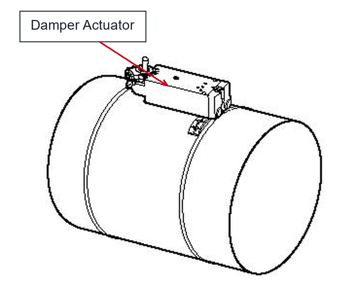
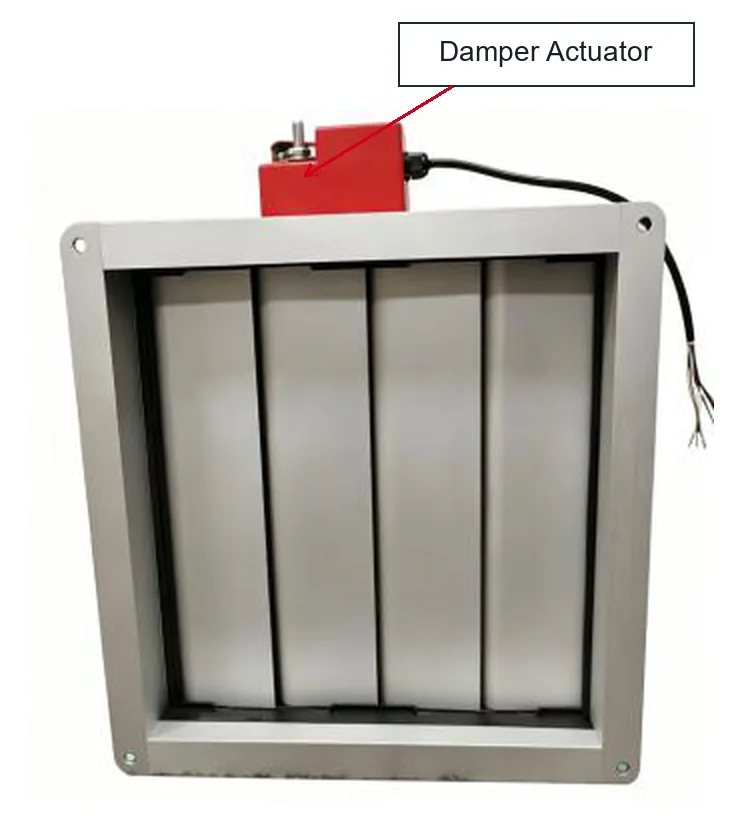
On a multi-blade damper, a single actuator drives a linkage that ties the blades together — which means the linkage, not the actuator, is often the thing that has gone out of adjustment when a damper no longer seals. Before condemning an actuator, check that the blades are free, that the coupling is tight on the shaft, and that the end stops are where they should be.
How to select a damper actuator
Four things decide whether the actuator you fit will still be working in five years.
- Torque. The actuator has to move the blade against more than its own weight: shaft friction, the linkage, and the aerodynamic force of the air pushing on the blade, which rises with duct velocity and with blade area. Specify the running torque you need, then leave margin — an actuator sized to the bare minimum will stall on the first stiff bearing. The damper actuator torque calculator works through the sizing from damper dimensions and conditions.
- Control signal. Match the actuator to the output the controller actually provides — switched, floating, or 0–10 V / 4–20 mA analogue. A mismatch here cannot be fixed in the field.
- Behaviour on power loss. Decide up front whether the damper must return to a rest position or stay where it is. On an exhaust or make-up air path, that choice is part of the safety case, not a preference.
- Environment. Ambient temperature, humidity, dust and wash-down all vary between a plant room, a car park and a livestock house. The enclosure rating and the operating temperature range should follow the location.
Two secondary points are worth a look as well: stroke time, because a very fast actuator on a large blade loads the linkage hard, and feedback output, if the BMS needs to display or trend actual blade position rather than assume it. For more on how the actuator sits inside a control loop, see our guide to what an HVAC control system is and how it works.
Summary
A damper actuator is a motor, a gear train, a limit mechanism, a position feedback element and a control board, packaged so that a fast, weak motor can turn a damper shaft through 0–90 ° with enough torque to move a blade against flowing air. At 0 ° the damper closes the duct; at 90 ° the blade lies parallel to the airflow and the duct is fully open.
Which of the three control modes you need — on/off, floating or modulating — follows from the controller and the duty, not from preference. And the applications run from public building ventilation and underground plant rooms through cleanrooms, process exhaust and dust collection to livestock houses, tunnels and solar shading. In every one of them the actuator’s job is the same: put the blade exactly where the controller asked, and keep doing it.
Work with DNARENS
DNARENS manufactures damper actuators and the rest of the terminal control layer these systems depend on — motorised valves and actuators, fan coil thermostats, and temperature, humidity and CO2 transmitters — from our own facility in Quanzhou, China, with OEM and ODM support and 100% function testing before shipment.
If you are specifying the air side of a project, these are the ranges that sit alongside a damper actuator:
- Damper actuators for round and rectangular dampers, in on/off, floating and 0–10 V modulating versions.
- Motorised valves and actuators for the water side, and FCU thermostats for terminal control.
- Temperature, humidity and CO2 transmitters for the measurement layer, including duct and room mounting.
Related reading: what an HVAC control system is and how it works, FCU thermostat wiring and commissioning and electric valve vs solenoid valve.
Send us the damper size, blade count, control signal and target market and our engineers will reply within 24 hours with matched models and a quotation: contact the DNARENS engineering team.
Free engineering tools, no sign-up: damper actuator torque calculator, analog signal calculator, control valve sizing calculator, FCU flow calculator and sensor range selector — all at danrens.com/tools.
Need Help Specifying or Sourcing?
Tell us your system type, required quantity and target market — our engineers reply within 24 hours with matched models and a quotation.
Back to Blog