
Overview
Most central air conditioning faults reported as “the thermostat is broken” turn out to be installation or wiring problems: a live and neutral landed the wrong way round, a valve conductor on the wrong terminal, or a unit that was never fixed securely to its wall box. The device itself is rarely the cause.
This guide covers the two families you will meet on real projects — mechanical and LCD (electronic) central AC thermostats — how each is installed, what every terminal is for, and the four wiring configurations that cover the majority of fan coil (water system) installations. If you already have the wiring done and need help proving the loop works, see our FCU thermostat wiring and commissioning field guide.
Key Points
- Central AC thermostats split into two families: mechanical, where a sensing element drives the contacts directly, and electronic LCD, where a sensor feeds programmed control logic.
- Both are built around the same industry-standard wall box: 86 × 86 × 37 mm.
- Typical control range is 18–28 °C. The thermostat holds the setpoint by switching or modulating a valve and the fan — not by switching the compressor.
- Four wiring configurations cover most water-side installations: two-wire motorised valve, on/off damper or three-wire valve, three-wire motorised valve with fan, and three-angle damper valve.
- VRF / direct-expansion systems are different: they ship with a wired controller and a plug-in connector, so there is no field wiring to a terminal block.
- The most common failure on site is not the device — it is which terminal the wire landed on.
What a Central AC Thermostat Actually Does
A central AC thermostat is a room-temperature controller that compares a measured room temperature against a setpoint and then commands the terminal equipment to close the gap. In a central system the terminal equipment is normally a fan coil unit, a motorised valve or a motorised damper — which is why the wiring is more involved than a domestic on/off thermostat that simply interrupts a compressor feed.
The market splits two ways, and the split matters because it changes both the installation sequence and the wiring:
| Type | How it senses and switches | How the setpoint is set | Typical application |
|---|---|---|---|
| Mechanical | A bimetal strip or vapour-filled bellows moves the switch contacts directly, without electronics | Rotary dial or slider, mechanically linked | Basic FCU rooms, plant rooms, retrofits where the simplest possible device is preferred |
| Electronic LCD | A thermistor measures temperature; a microcontroller drives relays, triacs or a 0–10 V output | Buttons, with a menu for mode, fan speed, time schedules and lock | Hotel guest rooms, offices, anywhere with scheduling, setback or BMS integration |
Within the electronic family there is a second split by display: units with an LCD screen showing room temperature, setpoint, mode and fan speed, and units with manual adjustment only (a dial or a set of buttons with indicator LEDs). The electrical interface is broadly the same; the difference is what the user can see and change.
Before You Start
- Isolate and prove dead. FCU thermostats are usually fed at 220–230 V AC. Isolate the fan coil circuit at the local isolator or the distribution board, then verify at the thermostat terminals — do not rely on the isolator label alone.
- Check the wall box. A standard 86 × 86 × 37 mm box is what these devices are designed to mount on. Confirm the box is level, clear of the wall finish, and deep enough for the wiring plus the power supply module.
- Confirm the cable schedule. At minimum expect a live, a neutral, a valve output and — in a fan coil installation — three fan speed conductors (high, medium, low).
- Label the conductors before you land them. Once a five- or seven-core flex disappears into a wall box, colour alone is not a reliable identifier.
- Read the terminal legend on the specific model. Terminal numbering is not standardised across manufacturers, and the layouts below are representative rather than universal.
Type 1 — Installing a Mechanical Thermostat
Mechanical thermostats have the advantage of simplicity: fewer conductors, no configuration menu, and nothing to program. The installation is three steps.
- Loosen every terminal screw on the unit. Slacken them before you start landing conductors, so you are not fighting a stiff screw with a wire already in place. Confirm each screw is present and threads cleanly — a stripped terminal on a mechanical unit is not field-repairable.
- Land the power conductors on the correct terminals. This is the step that prevents short circuits. Live and neutral must go to the terminals marked for the supply; the switched output goes to the valve or fan-coil control conductor. Keep individual strands tidy — a single stray strand bridging two terminals is a dead short the moment power is restored.
- Fix the body securely. Clip the unit onto the mounting plate or box and tighten the fixing screws, then check it cannot be lifted, rocked or pulled away from the wall. A thermostat that hangs off the wall distorts its own sensing element and will read the wall cavity rather than the room.
Two mechanical-specific points worth planning for:
- Mounting height and position. These devices sense the air moving past them, so avoid positions in direct sun, next to a door that opens to the outside, or immediately above a heat source. A mechanical thermostat cannot be corrected in software for a badly chosen position.
- Calibration. Most mechanical units provide a small calibration offset. Once the room has been stable for a few hours, compare the thermostat against a reference thermometer at the same height and apply the offset if the deviation is consistent.
Type 2 — Installing an LCD Thermostat
An LCD thermostat separates into a power supply box, an installation panel and the front panel that carries the display and the buttons. Installation follows three physical steps, and the wiring is done before the front panel goes on.
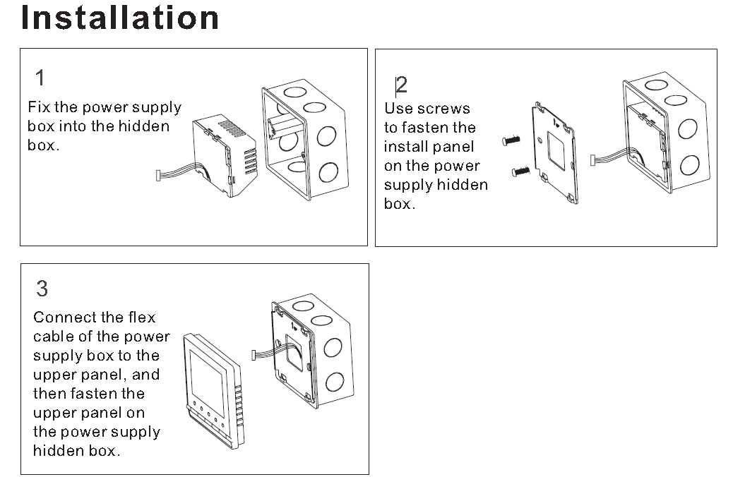
- Fix the power supply box into the wall box. The power supply module sits inside the hidden box and carries the terminal block. Bring the field conductors in through the box entry and dress them so they do not sit between the module and the wall.
- Fasten the installation panel to the power supply box. Screw the mounting panel down so the assembly is rigid. Check the panel is square — if it is skewed, the front panel will not clip on cleanly and the display will sit at an angle.
- Connect the flex cable, then fit the upper panel. The flexible cable carries power and signals between the supply box and the front panel. Seat the connector fully, then clip the upper panel onto the box. Do not trap or pinch the flex cable behind the panel.
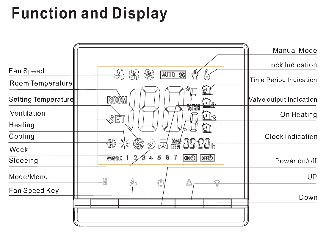
Once the panel is fitted, the device is configured entirely from the front buttons rather than by rewiring. The settings that matter at handover are:
- Power on/off — confirm the panel responds and the display initialises.
- Mode / menu — select cooling or heating to match the season and the valve wired to the output. Choosing the wrong mode will drive the valve in the wrong direction and the room will run away from setpoint.
- Fan speed — check each of the high, medium and low steps actually energises the correct fan conductor.
- Setpoint — set it according to the space and the design conditions, then confirm the valve output changes state as the room crosses the setpoint.
- Lock and time programs (where fitted) — set the key lock and any weekly schedule at commissioning, not later, so the handover includes them.
Terminal-by-Terminal Wiring
Terminal numbering differs between manufacturers, but the functions are consistent. Expect the following:
| Function | What it connects to | Notes |
|---|---|---|
| L | Live supply, 220–230 V AC | Feed from the isolated FCU circuit. Never share a neutral with a different circuit. |
| N | Neutral supply | Swapping L and N is the single most common cause of a dead unit or a short at first energisation. |
| Valve open / close | Motorised valve or damper actuator control conductors | On a three-wire valve, open and close are separate conductors and must not be transposed. |
| Valve (single output) | Two-wire motorised valve, or the switched leg of an AC valve | Used where the valve is spring-return and needs only a drive signal. |
| Fan high / medium / low | The three fan speed taps of the fan coil unit | Verify each tap individually. A transposed high and low is easy to miss on a visual check. |
| Sensor input (some models) | Remote or duct temperature sensor | Required where the thermostat is mounted away from the space it controls. |
| 0–10 V output (some models) | Modulating valve or damper actuator | See our notes on electric valve selection for HVAC if you are choosing between on/off and modulating duty. |
Three wiring rules that prevent most callbacks:
- Live, neutral and the valve conductors go to their own terminals — never bundle them onto a shared terminal to save space.
- Keep the low-voltage conductors physically separated from the mains conductors inside the box. A remote sensor cable run alongside a 230 V fan feed will pick up switching noise.
- Match the conductor gauge to the terminal rating. A conductor that is too thick will not clamp properly; too thin and the screw crushes it.
The Four Wiring Configurations
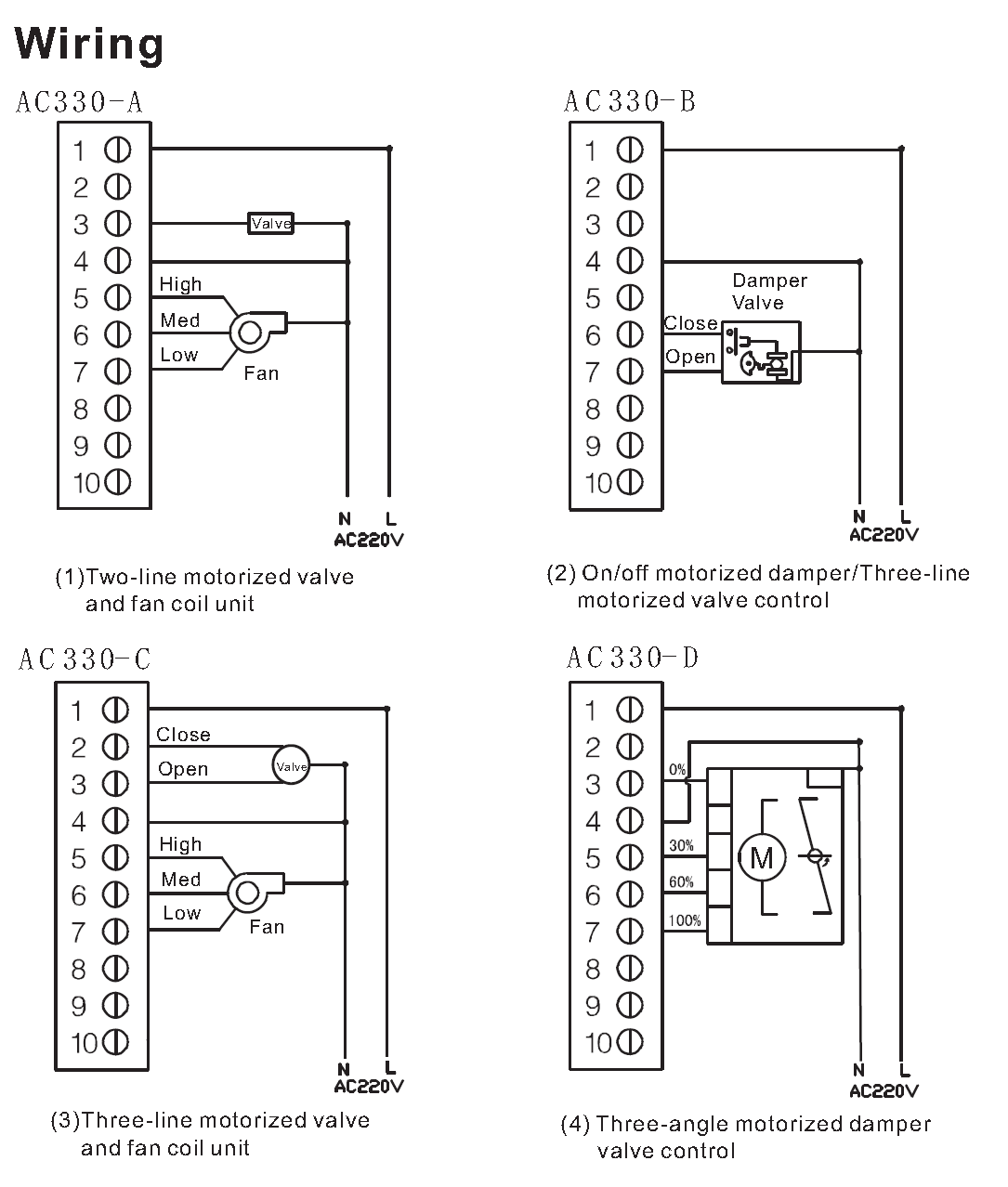
On the water side, almost every fan coil installation reduces to one of four arrangements. The diagram below shows all four on one terminal layout, with the same 10-way block used for each.
| Configuration | Valve or damper type | Fan control | Use it when |
|---|---|---|---|
| AC330-A | Two-line motorised valve (single drive output) | Three-speed: high, medium, low | The standard water-side FCU room. The valve is spring-return and needs only a drive signal, and the fan has three taps. |
| AC330-B | On/off motorised damper, or a three-line motorised valve with close and open conductors | None — no fan output used | Damper or isolation duty without a local fan, for example a zone damper or a valve on a plant-side loop. |
| AC330-C | Three-line motorised valve (close / open) | Three-speed: high, medium, low | The valve must be driven positively in both directions rather than spring-returned, and the room still has a three-speed fan coil. |
| AC330-D | Three-angle motorised damper valve with 0% / 30% / 60% / 100% positions | None — position outputs only | Stepped or modulating damper duty, where the actuator is commanded to discrete positions rather than simply open or closed. |
Whichever arrangement you are wiring, the sequence is the same: land the supply first, then the valve or damper conductors, then the fan taps. Testing in that order means a fault shows up on a circuit you can isolate, rather than on the whole assembly at once.
Water Systems and VRF Systems Are Not Wired the Same Way
The configurations above describe central AC terminal fan coil units on a water system, where the thermostat is a field-wired device. VRF / direct-expansion (refrigerant) systems work differently: the indoor unit is supplied with a purpose-made wired controller and a plug-in connector. There is no terminal block to land conductors on — the connector is plugged in and the unit is ready.
That distinction is worth confirming before you buy. If the project is a water-side FCU installation, specify a thermostat with the terminal layout that matches the valve and fan arrangement on site. If it is a VRF installation, the controller normally comes with the indoor unit, and a third-party thermostat is only relevant if the system exposes a dry-contact or bus interface for third-party control.
Commissioning Checklist
- Visual check before energising. No stray strands bridging terminals, no conductor trapped under the module, front panel seated and clipped.
- Energise and confirm the display. An LCD unit should initialise and show room temperature. A mechanical unit should show no signs of heat or smell.
- Test the valve output both ways. Change mode between cooling and heating, or drive the setpoint past the room temperature in each direction, and confirm the valve or damper moves to the expected position.
- Test each fan speed individually. High, medium and low, one at a time, confirming airflow changes at each step.
- Verify the room temperature reading. Compare against a reference thermometer at the same height, after the room has been stable for a few hours.
- Set the lock and schedule. If the model supports a key lock or weekly program, configure and demonstrate it at handover.
- Record the wiring. Photograph the terminal block and write the conductor schedule into the handover pack. The next engineer will need it, and it takes thirty seconds.
Common Mistakes
| Mistake | What you see | Fix |
|---|---|---|
| Live and neutral transposed | Unit dead, or the breaker trips on first energisation | Re-check against the terminal legend before powering up, not after |
| A stray strand bridging two terminals | Intermittent short, often only when the box is closed | Re-terminate with the correct strip length; inspect with the module loose |
| Valve conductors transposed on a three-wire valve | Valve drives the wrong way — heats when it should cool | Confirm open and close against the actuator’s own terminals, not the thermostat legend alone |
| High and low fan taps swapped | Fan works, but the speeds are backwards | Test each tap individually rather than assuming a working fan means correct wiring |
| Front panel clipped on before testing | A fault is found after the box is closed and the wall is finished | Commission on the open assembly, then fit the panel |
| Mechanical unit mounted in direct sun | Room reads several degrees high in the afternoon only | Relocate. No software correction is available on a mechanical device |
| Wrong mode selected at handover | Valve drives opposite to the season and the room drifts | Set cooling or heating mode as part of the commissioning sequence |
FAQ
Q: Can I use a standard 86 × 86 × 37 mm wall box?
A: Yes. That is the box size these thermostats are designed around. Check the depth is enough for the wiring plus the power supply module, especially if you are also bringing a remote sensor cable into the same box.
Q: What is the difference between a mechanical and an electronic thermostat in practice?
A: A mechanical unit senses and switches directly, with a dial setpoint and no configuration. An electronic LCD unit uses a thermistor plus programmed logic, which adds scheduling, setback, key lock, fan-speed control and often a 0–10 V or bus output. Mechanically they mount the same way; electrically the electronic unit has more terminals to land.
Q: How do I know which of the four configurations applies to my installation?
A: Identify the valve first. A two-wire spring-return valve with a three-speed fan is AC330-A. A three-wire valve driven in both directions with a three-speed fan is AC330-C. A damper or valve with no local fan is AC330-B. A damper actuator commanded to discrete positions is AC330-D.
Q: Do VRF systems need a third-party thermostat?
A: Not for normal operation. VRF indoor units are supplied with a wired controller that plugs in, so there is no terminal block wiring to do. A third-party thermostat is only relevant where the system exposes a dry-contact or bus interface for external control.
Q: The room never reaches setpoint after installation. Where do I start?
A: Check the mode setting and the valve direction first, then the fan speed output. Those three cover the majority of “new thermostat, no control” calls. If all three are correct, move to the system side — flow, valve authority and coil condition.
Summary
Mechanical and LCD central AC thermostats mount on the same 86 mm box, but they are installed differently: a mechanical unit is a three-step job of slackening terminals, landing the conductors correctly and fixing the body securely, while an LCD unit adds a power supply module, an installation panel and a plug-in flex cable before any settings are made. On the wiring side, live, neutral and the valve conductors each belong on their own terminal, and almost every water-side FCU installation reduces to one of four configurations. Get the terminal allocation right, test each output individually, and the thermostat will do the rest.
Work with DNARENS
DNARENS manufactures the control layer for water-side and VRF HVAC projects: FCU thermostats including the AC3385 touch model and the AC006, AC306 and AC308, together with motorised ball valves, motorised valves, modulating damper actuators and 0–10 V temperature, humidity and CO2 transmitters — from our own facility in Quanzhou, China, with OEM and ODM support. Every unit is 100% function-tested before shipment, and third-party certification can be arranged for the destination market on request.
Free engineering tools, no sign-up: FCU flow calculator, valve Cv calculator, damper actuator torque calculator, analog signal calculator and sensor range selector — all at danrens.com/tools.
Send us your valve and fan arrangement and target market and our engineers will come back with matched models and a quotation: Contact our engineering team.
Need Help Specifying or Sourcing?
Tell us your system type, required quantity and target market — our engineers reply within 24 hours with matched models and a quotation.
Back to Blog
